Delays in Arduino play a very big role. Without them, even the simplest example of Blink, which blinks an LED after a specified period of time, cannot work. But most novice programmers know little about time delays and use only Arduino delay without knowing the side effects of this command. In this article, I will talk in detail about timing functions and how to use them in the Arduino IDE.
There are several different commands in Arduino that are responsible for working with time and pauses:
- delay()
- delayMicroseconds()
- millis()
- micros()
They differ in accuracy and have their own characteristics that should be taken into account when writing code.
Using the arduino delay function
Syntax
Arduino delay is the simplest command and is most often used by beginners. Essentially, it is a delay that pauses the program for the number of milliseconds indicated in parentheses. (There are 1000 milliseconds in one second.) The maximum value can be 4294967295 ms, which is approximately equal to 50 days. Let's look at a simple example that clearly shows how this command works.
Void setup() ( pinMode(13, OUTPUT); ) void loop() ( digitalWrite(13, HIGH); // send a high signal to pin 13 delay(10000); // pause 10000ms or 10 seconds digitalWrite13, LOW); // send a low signal to pin 13 delay(10000); // pause 10000ms or 10 seconds)
In method setup We specify that pin 13 will be used as an output. In the main part of the program, a high signal is first sent to the pin, then we make a delay of 10 seconds. During this time, the program seems to be suspended. Then a low signal is given and again there is a delay and everything starts all over again. As a result, we get that the pin is alternately supplied with either 5 V or 0.
You need to clearly understand that during a pause using delay, the program’s work is suspended, the application will not receive any data from the sensors. This is the biggest disadvantage of using the Arduino delay function. You can get around this limitation using interrupts, but we will talk about this in a separate article.
Example of delay with blinking LED
 An example circuit to illustrate how the delay function works.
You can build a circuit with an LED and a resistor. Then we will have a standard example - blinking an LED. To do this, you need to connect an LED with a positive contact to the pin, which we designated as output. We connect the free leg of the LED to ground through a resistor of approximately 220 Ohms (a little more is possible). You can determine the polarity by looking at its insides. The large cup inside is connected to the minus, and the small leg to the plus. If your LED is new, then you can determine the polarity by the length of the leads: the long leg is plus, the short leg is minus.
delayMicroseconds function
This function is a complete analogue of delay, except that its units of measurement are not milliseconds, but microseconds (in 1 second there are 1,000,000 microseconds). The maximum value will be 16383, which is equal to 16 milliseconds. The resolution is 4, that is, the number will always be a multiple of four. An example snippet would look like this:
DigitalWrite(2, HIGH); // send a high signal to pin 2 delayMicroseconds(16383); // pause 16383 µs digitalWrite(2, LOW); // send a low signal to pin 2 delayMicroseconds(16383); // pause 16383 µs
The problem with delayMicroseconds is exactly the same as with delay - these functions completely “hang” the program and it literally freezes for a while. At this time, it is impossible to work with ports, read information from sensors and perform mathematical operations. This option is suitable for flashing lights, but experienced users do not use it for large projects, since such failures are not needed there. Therefore, it is much better to use the functions described below.
Millis function instead of delay
The millis() function will allow you to perform a delay without delay on the Arduino, thereby circumventing the shortcomings of the previous methods. The maximum value of the millis parameter is the same as that of the delay function (4294967295ms or 50 days).
Using millis, we do not stop the execution of the entire sketch, but simply indicate how long the Arduino should simply “bypass” the exact block of code that we want to pause. Unlike delay millis, it doesn't stop anything by itself. This command simply returns to us from the microcontroller’s built-in timer the number of milliseconds that have passed since the start. With each call to loop, we ourselves measure the time that has passed since the last call of our code and if the time difference is less than the desired pause, then we ignore the code. As soon as the difference becomes greater than the required pause, we execute the code, get the current time using the same millis and remember it - this time will be the new starting point. In the next cycle, the countdown will already be from the new point and we will again ignore the code until the new difference between millis and our previously saved value reaches the desired pause again.
Delay without delay using millis requires more code, but with its help you can blink an LED and pause a sketch without stopping the system.
Here is an example that clearly illustrates the work of the team:
Unsigned long timing; // Variable for storing the reference point void setup() ( Serial.begin(9600); ) void loop() ( /* At this point the execution of the delay() analog begins. Calculate the difference between the current moment and the previously saved reference point. If the difference is greater the desired value, then execute the code. If not, do nothing */ if (millis() - timing > 10000)( // Instead of 10000, substitute the pause value you need timing = millis(); Serial.println ("10 seconds") ; ) )
First we introduce the timing variable, which will store the number of milliseconds. By default, the value of the variable is 0. In the main part of the program, we check the condition: if the number of milliseconds from the start of the microcontroller minus the number written in the timing variable is greater than 10000, then the action of outputting a message to the port monitor is performed and the current time value is written to the variable. As a result of the program's operation, the message 10 seconds will be displayed on the port monitor every 10 seconds. This method allows you to blink the LED without delay.
Micros function instead of delay
This function can also perform a delay without using the delay command. It works exactly the same as millis, but it counts microseconds rather than milliseconds with a resolution of 4 μs. Its maximum value is 4294967295 microseconds or 70 minutes. If it overflows, the value is simply reset to 0, don't forget about it.
Summary
The Arduino platform provides us with several ways to implement a delay in our project. Using delay, you can quickly pause the execution of a sketch, but at the same time you will block the operation of the microcontroller. Using the millis command allows you to do without delay in Arduino, but this will require a little more programming. Choose the best method depending on the complexity of your project. As a rule, in simple sketches and with a delay of less than 10 seconds, delay is used. If the operating logic is more complex and a large delay is required, then it is better to use millis instead of delay.
" presents the training course "Arduino for Beginners". The series consists of 10 lessons, as well as additional material. Lessons include text instructions, photos and instructional videos. In each lesson you will find a list of required components, a program listing and a connection diagram. Once you've completed these 10 basic lessons, you'll be able to move on to more interesting models and building of Arduino-based robots. The course is aimed at beginners; no additional information from electrical engineering or robotics is required to begin it.
Brief information about Arduino
What is Arduino?
Arduino (Arduino) is a hardware computing platform, the main components of which are an input-output board and a development environment. Arduino can be used to create stand-alone interactive objects, or connect to software running on a computer. Arduino is a single board computer.
How are Arduino and robots connected?
The answer is very simple - Arduino is often used as robot brain.
The advantage of Arduino boards over similar platforms is their relatively low price and almost widespread distribution among amateurs and professionals in robotics and electrical engineering. Once you get into Arduino, you will find support in any language and like-minded people who will answer your questions and discuss your developments with.
Lesson 1. Flashing LED on Arduino
 In the first lesson you will learn how to connect an LED to an Arduino and control it to blink. This is the simplest and most basic model.
Light-emitting diode- a semiconductor device that creates optical radiation when an electric current is passed through it in the forward direction.
Lesson 2. Connecting a button on Arduino

 In this tutorial you will learn how to connect a button and an LED to an Arduino.
When the button is pressed, the LED will light up; when the button is pressed, it will not light up. This is also the base model.
Lesson 3. Connecting a potentiometer on Arduino
 In this tutorial you will learn how to connect a potentiometer to Arduino.
Potentiometer- This resistor with adjustable resistance.Potentiometers are used as regulators of various parameters - sound volume, power, voltage, etc.This is also one of the basic schemes. In our model from turning the potentiometer knobThe brightness of the LED will depend.
Lesson 4. Servo control on Arduino
 In this tutorial you will learn how to connect a servo to an Arduino.
Servois a motor whose shaft position can be controlled by setting the angle of rotation.
Servos are used to simulate various mechanical movements of robots.
Lesson 5. Three-color LED on Arduino
 In this tutorial you will learn how to connect a tri-color LED to an Arduino.
Tri-color LED(rgb led) - these are three LEDs of different colors in one housing. They come either with a small printed circuit board on which resistors are located, or without built-in resistors. The lesson covers both options.
Lesson 6. Piezoelectric element on Arduino
 In this lesson you will learn how to connect a piezo element to an Arduino.
Piezo element- an electromechanical converter that translates electrical voltage into membrane vibration. These vibrations create sound.
In our model, the sound frequency can be adjusted by setting the appropriate parameters in the program.
Lesson 7. Photoresistor on Arduino
 In this lesson of our course you will learn how to connect a photoresistor to Arduino.
Photoresistor- a resistor whose resistance depends on the brightness of the light falling on it.
In our model, the LED lights up only if the brightness of the light above the photoresistor is less than a certain one; this brightness can be adjusted in the program.
Lesson 8. Motion sensor (PIR) on Arduino. Automatic sending of E-mail
In this lesson of our course you will learn how to connect a motion sensor (PIR) to Arduino, as well as organize automatic sending of e-mail. 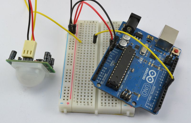
Motion sensor (PIR)- infrared sensor to detect movement or presence of people or animals.
In our model, when receiving a signal about human movement from a PIR sensor, Arduino sends a command to the computer to send an E-mail and the letter is sent automatically.
Lesson 9. Connecting a temperature and humidity sensor DHT11 or DHT22
In this lesson of ours, you will learn how to connect a DHT11 or DHT22 temperature and humidity sensor to an Arduino, and also become familiar with the differences in their characteristics. 
Temperature and humidity sensor is a composite digital sensor consisting of a capacitive humidity sensor and a thermistor for measuring temperature.
In our model, Arduino reads the sensor readings and displays the readings on the computer screen.
Lesson 10. Connecting a matrix keyboard
 In this lesson of our course, you will learn how to connect a matrix keyboard to an Arduino board, and also get acquainted with various interesting circuits.
Matrix keyboard invented to simplify the connection of a large number of buttons. Such devices are found everywhere - in computer keyboards, calculators, and so on.
Lesson 11. Connecting the DS3231 real-time clock module
In the last lesson of our course, you will learn how to connect a real-time clock module from the family  DS to the Arduino board, and also get acquainted with various interesting circuits.
Real time clock module- this is an electronic circuit designed to record chronometric data (current time, date, day of the week, etc.), and is a system consisting of an autonomous power source and a recording device.
Application. Ready-made frames and Arduino robots
 You can start learning Arduino not only from the board itself, but also by purchasing a ready-made, full-fledged robot based on this board - a spider robot, a robot car, a turtle robot, etc. Such way It is also suitable for those who are not particularly attracted to electrical circuits.
By purchasing a working robot model, i.e. in fact, a ready-made high-tech toy can awaken interest in independent design and robotics. The openness of the Arduino platform allows you to make new toys from the same components.
Another option is to purchase a robot frame or body: a platform on wheels or a track, a humanoid, a spider, etc. In this case, you will have to do the stuffing of the robot yourself.
Application. Mobile directory
 – an assistant for developers of algorithms for the Arduino platform, the purpose of which is to give the end user the opportunity to have a mobile set of commands (reference book).
The application consists of 3 main sections:
- Operators;
- Data;
- Functions.
Where to buy Arduino
 Arduino kits
The course will be updated with additional lessons. Follow us
Today we will talk about using SD and micro SD cards in Arduino. We will figure out how to connect SD cards to Arduino, how to write and read information. Using extra memory can be very useful in many projects. If you do not know what SPI, I2C and analog pins are, then I advise you to watch past lessons and understand these Arduino communication interfaces.
In this tutorial we will talk about wireless communication between two Arduino boards. This can be very useful for passing commands from one Arduino to another, or exchanging information between your DIYs. The possibility of wireless data transmission opens up new opportunities in creating your projects.
In this tutorial we will learn about the I2C bus. I2C is a communication bus that uses only two lines. Using this interface, Arduino can communicate with many devices over two wires. Today we will figure out how to connect sensors to Arduino via the I2C bus, how to access a specific device and how to receive data from these devices.
In this tutorial we will talk about the Arduino Serial communication interface. We have already used this interface in previous lessons, when we displayed values from sensors on the computer screen. Today we will take a closer look at how this connection works, and we will also learn how to use the data transferred to the computer port monitor using Processing.
Today we will talk about transistors and connecting loads to Arduino. Arduino itself cannot produce a voltage higher than 5 volts and a current higher than 40 mA from one pin. This is enough for sensors and LEDs, but if we want to connect devices that are more current-demanding, we will have to use transistors or relays.
In this lesson we will talk about the basics of circuit design as applied to Arduino. And let's start, of course, with Ohm's law, since this is the basis of all circuitry. Also in this lesson we will talk about resistance, pull-up and pull-up resistors, calculation of current and voltage.
In this article, I decided to put together a complete step-by-step guide for Arduino beginners. We will look at what Arduino is, what you need to start learning, where to download and how to install and configure the programming environment, how it works and how to use the programming language, and much more that is necessary to create full-fledged complex devices based on the family of these microcontrollers.
Here I will try to give a condensed minimum so that you understand the principles of working with Arduino. For a more complete immersion in the world of programmable microcontrollers, pay attention to other sections and articles of this site. I will leave links to other materials on this site for a more detailed study of some aspects.
What is Arduino and what is it for?
Arduino is an electronic construction kit that allows anyone to create a variety of electro-mechanical devices. Arduino consists of software and hardware. The software part includes a development environment (a program for writing and debugging firmware), many ready-made and convenient libraries, and a simplified programming language. The hardware includes a large line of microcontrollers and ready-made modules for them. Thanks to this, working with Arduino is very easy!
With the help of Arduino you can learn programming, electrical engineering and mechanics. But this is not just an educational constructor. Based on it, you can make really useful devices.
Starting from simple flashing lights, weather stations, automation systems and ending with smart home systems, CNC machines and unmanned aerial vehicles. The possibilities are not even limited by your imagination, because there are a huge number of instructions and ideas for implementation.
Arduino Starter Kit
In order to start learning Arduino, you need to acquire the microcontroller board itself and additional parts. It is best to purchase an Arduino starter kit, but you can choose everything you need yourself. I recommend choosing a set because it's easier and often cheaper. Here are links to the best sets and individual parts that you will definitely need to study:
| Basic Arduino kit for beginners: | Buy |
| Large set for training and first projects: | Buy |
| Set of additional sensors and modules: | Buy |
| Arduino Uno is the most basic and convenient model from the line: | Buy |
| Solderless breadboard for easy learning and prototyping: | Buy |
| Set of wires with convenient connectors: | Buy |
| LED set: | Buy |
| Resistor kit: | Buy |
| Buttons: | Buy |
| Potentiometers: | Buy |
Arduino IDE development environment
To write, debug and download firmware, you need to download and install the Arduino IDE. This is a very simple and convenient program. On my website I have already described the process of downloading, installing and configuring the development environment. Therefore, here I will simply leave links to the latest version of the program and to
| Version | Windows | Mac OS X | Linux |
| 1.8.2 |
Arduino programming language
When you have a microcontroller board in your hands and a development environment installed on your computer, you can start writing your first sketches (firmware). To do this, you need to become familiar with the programming language.
Arduino programming uses a simplified version of the C++ language with predefined functions. As in other C-like programming languages, there are a number of rules for writing code. Here are the most basic ones:
- Each instruction must be followed by a semicolon (;)
- Before declaring a function, you must specify the data type returned by the function, or void if the function does not return a value.
- It is also necessary to indicate the data type before declaring a variable.
- Comments are designated: // Inline and /* block */
You can learn more about data types, functions, variables, operators and language constructs on the page on You do not need to memorize and remember all this information. You can always go to the reference book and look at the syntax of a particular function.
All Arduino firmware must contain at least 2 functions. These are setup() and loop().
setup function
In order for everything to work, we need to write a sketch. Let's make the LED light up after pressing the button, and go out after the next press. Here's our first sketch:
// variables with pins of connected devices int switchPin = 8; int ledPin = 11; // variables to store the state of the button and LED boolean lastButton = LOW; boolean currentButton = LOW; boolean ledOn = false; void setup() ( pinMode(switchPin, INPUT); pinMode(ledPin, OUTPUT); ) // function for debouncing boolean debounse(boolean last) ( boolean current = digitalRead(switchPin); if(last != current) ( delay (5); current = digitalRead(switchPin); ) return current; ) void loop() ( currentButton = debounse(lastButton); if(lastButton == LOW && currentButton == HIGH) ( ledOn = !ledOn; ) lastButton = currentButton ; digitalWrite(ledPin, ledOn); )
// variables with pins of connected devices int switchPin = 8 ; int ledPin = 11 ; // variables to store the state of the button and LED boolean lastButton = LOW ; boolean currentButton = LOW ; boolean ledOn = false ; void setup() ( pinMode(switchPin, INPUT); pinMode(ledPin, OUTPUT); // function for debouncing boolean debounse (boolean last ) ( boolean current = digitalRead(switchPin); if (last != current ) ( delay(5); current = digitalRead(switchPin); return current ; void loop() ( currentButton = debounse(lastButton); if (lastButton == LOW && currentButton == HIGH ) ( ledOn = ! ledOn; lastButton = currentButton ; digitalWrite(ledPin, ledOn); |
In this sketch, I created an additional debounse function to suppress contact bounce. There is information about contact bounce on my website. Be sure to check out this material.
PWM Arduino
Pulse width modulation (PWM) is the process of controlling voltage using the duty cycle of a signal. That is, using PWM we can smoothly control the load. For example, you can smoothly change the brightness of an LED, but this change in brightness is obtained not by decreasing the voltage, but by increasing the intervals of the low signal. The operating principle of PWM is shown in this diagram:

When we apply PWM to the LED, it starts to quickly light up and go out. The human eye is not able to see this because the frequency is too high. But when shooting video, you will most likely see moments when the LED is not lit. This will happen provided that the camera frame rate is not a multiple of the PWM frequency.
Arduino has a built-in pulse width modulator. You can use PWM only on those pins that are supported by the microcontroller. For example, Arduino Uno and Nano have 6 PWM pins: these are pins D3, D5, D6, D9, D10 and D11. The pins may differ on other boards. You can find a description of the board you are interested in in
To use PWM in Arduino there is a function. It takes as arguments the pin number and the PWM value from 0 to 255. 0 is 0% fill with a high signal, and 255 is 100%. Let's write a simple sketch as an example. Let's make the LED light up smoothly, wait one second and fade out just as smoothly, and so on ad infinitum. Here is an example of using this function:
// The LED is connected to pin 11 int ledPin = 11; void setup() ( pinMode(ledPin, OUTPUT); ) void loop() ( for (int i = 0; i< 255; i++) { analogWrite(ledPin, i); delay(5); } delay(1000); for (int i = 255; i >0; i--) ( analogWrite(ledPin, i); delay(5); ) )
// LED connected to pin 11 int ledPin = 11 ; void setup() ( pinMode(ledPin, OUTPUT); void loop() ( for (int i = 0 ; i< 255 ; i ++ ) { analogWrite(ledPin, i); delay(5); delay(1000); for (int i = 255; i > 0; i -- ) ( |
This simulator works best on the Chrome browser
Let's take a closer look at Arduino.
Arduino is not a large computer that can be connected to external circuits. Arduino Uno uses Atmega 328P
This is the largest chip on the board. This chip executes programs that are stored in its memory. You can download the program via usb using Arduino IDE. The USB port also provides power to the arduino.
There is a separate power connector. The board has two pins labeled 5v and 3.3v, which are needed to power various devices. You will also find pins marked GND, these are the ground pins (ground is 0V). The Arduino platform also has 14 digital pins, labeled 0 to 13, which connect to external nodes and have two states, high or low (on or off). These contacts can work as outputs or as inputs, i.e. they can either transmit some data and control external devices, or receive data from devices. The next pins on the board are labeled A0-A5. These are analog inputs that can receive data from various sensors. This is especially convenient when you need to measure a certain range, such as temperature. The analog inputs have additional functions that can be enabled separately.

How to use a development board.
The breadboard is needed to temporarily connect the parts, check how the device works, before you solder everything together.
All of the following examples are assembled on a breadboard so that you can quickly make changes to the circuit and reuse parts without bothering with soldering.
The breadboard has rows of holes into which you can insert parts and wires. Some of these holes are electrically connected to each other.
The two top and bottom rows are connected in rows along the entire board. These rows are used to supply power to the circuit. It could be 5V or 3.3V, but either way, the first thing you need to do is connect 5V and GND to the breadboard as shown in the picture. Sometimes these row connections may be broken in the middle of the board, then if you need to, you can connect them as shown in the picture.


The remaining holes, located in the middle of the board, are grouped into groups of five holes. They are used to connect circuit parts.

The first thing we will connect to our microcontroller is an LED. The electrical connection diagram is shown in the picture.

Why is a resistor needed in a circuit? In this case, it limits the current that passes through the LED. Each LED is designed for a certain current, and if this current is higher, the LED will fail. You can find out what value the resistor should be using Ohm's law. For those who don’t know or have forgotten, Ohm’s law says that there is a linear relationship between current and voltage. That is, the more voltage we apply to the resistor, the more current will flow through it.
V=I*R
Where V- voltage across the resistor
I- current through the resistor
R- resistance that needs to be found.
First, we must find out the voltage across the resistor. Most 3mm or 5mm LEDs you will use have an operating voltage of 3V. This means that we need to extinguish 5-3 = 2V at the resistor.
We will then calculate the current passing through the resistor.
Most 3mm and 5mm LEDs glow at full brightness at 20mA. A current greater than this can disable them, while a current of lesser intensity will reduce their brightness without causing any harm.
So, we want to connect the LED to the 5V circuit so that it carries a current of 20mA. Since all the parts are included in one circuit, the resistor will also have a current of 20mA.
We get
2V = 20 mA * R
2V = 0.02A * R
R = 100 Ohm
100 Ohms is the minimum resistance, it is better to use a little more, because LEDs have some variation in characteristics.
In this example, a 220 ohm resistor is used. Only because the author has a lot of them: wink: .
Insert the LED into the holes in the middle of the board so that its long lead is connected to one of the resistor leads. Connect the second end of the resistor to 5V, and connect the second lead of the LED to GND. The LED should light up.
Please note that there is a difference in how you connect the LED. Current flows from the longer terminal to the shorter one. In the diagram you can imagine that the current flows in the direction where the triangle is directed. Try turning the LED upside down and you will see that it will not light up.
But how you connect the resistor makes no difference at all. You can turn it over or try connecting it to a different pin of the LED, this will not affect the operation of the circuit. It will still limit the current through the LED.
Anatomy of Arduino Sketch.
Programs for Arduino are called sketch. They consist of two main functions. Function setup and function loop
Inside this function you will set all the basic settings. Which pins will work as input or output, which libraries to connect, initialize variables. Function Setup() runs only once during the sketch, when program execution starts.
this is the main function that is executed after setup(). In fact, it is the program itself. This function will run indefinitely until you turn off the power.
Arduino flashing LED

In this example, we will connect an LED circuit to one of the Arduino's digital pins and turn it on and off using a program, and you will also learn several useful functions.


This function is used in setup() part of the program and serves to initialize the pins that you will use as input (INPUT) or exit (OUTPUT). You will not be able to read or write data from the pin until you set it to respectively pinMode. This function has two arguments: pinNumber is the pin number you will use.
Mode-sets how the pin will work. At the entrance (INPUT) or exit (OUTPUT). To light the LED we must give a signal FROM Arduino. To do this, we configure the output pin.
- this function is used to set the state (state) pina (pinNumber). There are two main states (actually 3 of them), one is HIGH, there will be 5V on the pin, that’s something else Low and the pin will be 0v. This means that in order to light the LED we need to set the pin connected to the LED to a high level HIGH.
Delay. Serves to delay the operation of the program for a period specified in msec.
Below is the code that makes the LED blink.
//LED Blink int ledPin = 7;//Arduino pin to which the LED is connected void setup() ( pinMode(ledPin, OUTPUT);// setting the pin as OUTPUT) void loop() ( digitalWrite(ledPin, HIGH);// turn on the LED delay(1000);// delay 1000 ms (1 sec) digitalWrite(ledPin, LOW);//Turn off the LED delay(1000);//wait 1 sec)
Small explanations on the code.
Lines that start with "//" are comments and are ignored by Arduino.
All commands end with a semicolon; if you forget them, you will receive an error message.
ledPin is a variable. Variables are used in programs to store values. In this example, the variable ledPin the value is assigned to 7, this is the Arduino pin number. When the Arduino program encounters a line with a variable ledPin, it will use the value we specified earlier.
So record pinMode(ledPin, OUTPUT) similar to recording pinMode(7, OUTPUT).
But in the first case, you just need to change the variable and it will change in each line where it is used, and in the second case, in order to change the variable, you will have to make changes manually in each command.
The first line indicates the type of the variable. When programming Arduino, it is important to always declare the type of variables. For now it is enough for you to know that INT announces negative and positive numbers.
Below is a simulation of the sketch. Click start to see the circuit in action.
As expected, the LED goes out and comes back on after one second. Try changing the delay to see how it works.
Control of multiple LEDs.
In this example, you will learn how to control multiple LEDs. To do this, install 3 more LEDs on the board and connect them to resistors and Arduino pins as shown below.
In order to turn the LEDs on and off one by one, you need to write a program similar to this:
//Multi LED Blink int led1Pin = 4; int led2Pin = 5; int led3Pin = 6; int led4Pin = 7; void setup() ( //set pins as OUTPUT pinMode(led1Pin, OUTPUT); pinMode(led2Pin, OUTPUT); pinMode(led3Pin, OUTPUT); pinMode(led4Pin, OUTPUT); ) void loop() ( digitalWrite(led1Pin, HIGH );//turn on the LED delay(1000);//delay 1 sec digitalWrite(led1Pin, LOW);//turn off the LED delay(1000);//delay 1 sec //do the same for the other 3 LEDs digitalWrite(led2Pin , HIGH);//light the LED delay(1000);//delay 1 sec digitalWrite(led2Pin, LOW);//extinguish the LED delay(1000);//delay 1 sec digitalWrite(led3Pin, HIGH);//light the LED delay(1000);// delay 1 sec digitalWrite(led3Pin, LOW);//extinguish the LED delay(1000);//delay 1 sec digitalWrite(led4Pin, HIGH);//turn on the LED delay(1000);// delay 1 sec digitalWrite(led4Pin, LOW);//extinguish the LED delay(1000);//delay 1 sec)
This program will work great, but it is not the most rational solution. The code needs to be changed. In order for the program to work over and over again, we will use a construction called .
Loops are useful when you need to repeat the same action several times. In the code above we repeat the lines
DigitalWrite(led4Pin, HIGH); delay(1000); digitalWrite(led4Pin, LOW); delay(1000);
full sketch code in attachment (downloads: 1260)
LED brightness adjustment
Sometimes you will need to change the brightness of the LEDs in the program. This can be done using the command analogWrite()
. This command turns the LED on and off so quickly that the eye cannot see the flickering. If the LED is turned on half the time and off half the time, it will visually appear that it is glowing at half its brightness. This is called pulse width modulation (PWM or PWM in English). Shim is used quite often, since it can be used to control an “analog” component using a digital code. Not all Arduino pins are suitable for these purposes. Only those conclusions near which such a designation is drawn " ~
". You will see it next to pins 3,5,6,9,10,11.
Connect one of your LEDs to one of the PWM pins (for the author this is pin 9). Now run the LED flashing sketch, but first change the command digitalWrite() on analogWrite(). analogWrite() has two arguments: the first is the pin number, and the second is the PWM value (0-255), in relation to LEDs this will be their brightness, and for electric motors the rotation speed. Below is an example code for different LED brightnesses.
//Change the brightness of the LED int ledPin = 9;//an LED is connected to this pin void setup() ( pinMode(ledPin, OUTPUT);// initializing the pin to the output ) void loop() ( analogWrite(ledPin, 255);// full brightness (255/255 = 1) delay(1000);//pause 1 sec digitalWrite(ledPin, LOW);//turn off LED delay(1000);//pause 1 sec analogWrite(ledPin, 191);//brightness by 3/4 (191/255 ~= 0.75) delay(1000);//pause 1 sec digitalWrite(ledPin, LOW);//turn off the LED delay(1000);//pause 1 sec analogWrite(ledPin, 127); //half brightness (127/255 ~= 0.5) delay(1000);//pause 1 sec digitalWrite(ledPin, LOW);//turn off LED delay(1000);//pause 1 sec analogWrite(ledPin, 63); //quarter brightness (63/255 ~= 0.25) delay(1000);//pause 1 sec digitalWrite(ledPin, LOW);//turn off the LED delay(1000);//pause 1 sec)
Try changing the PWM value in the command analogWrite() to see how this affects brightness.
Next, you will learn how to adjust the brightness smoothly from full to zero. You can, of course, copy a piece of code 255 times
analogWrite(ledPin, brightness); delay(5);//short delay brightness = brightness + 1;
But, you understand, this will not be practical. The best way to do this is to use the FOR loop we used earlier.
The following example uses two loops, one to decrease the brightness from 255 to 0
for (int brightness=0;brightness=0;brightness--)( analogWrite(ledPin,brightness); delay(5); )
delay(5) used to slow down the brightness fade-in speed 5*256=1280ms=1.28s)
The first line uses " brightness-" to make the brightness value decrease by 1 each time the loop is repeated. Note that the loop will run until brightness >=0.Replacing the sign >
on the sign >=
we included 0 in the brightness range. This sketch is modeled below. //smoothly change the brightness int ledPin = 9;//an LED is connected to this pin void setup() ( pinMode(ledPin, OUTPUT);// initialization of the output pin) void loop() ( //smoothly increase the brightness (0 to 255 ) for (int brightness=0;brightness=0;brightness--)( analogWrite(ledPin,brightness); delay(5); ) delay(1000);//wait 1 sec //smoothly reduce brightness (255 to 0) for (int brightness=255;brightness>=0;brightness--)( analogWrite(ledPin,brightness); delay(5); ) delay(1000);//wait 1 sec ) )
It's not very visible, but the idea is clear.
RGB LED and Arduino
An RGB LED is actually three different colored LEDs in one package.

By including different LEDs with different brightnesses, you can combine them to create different colors. For Arduino, where the number of brightness levels is 256, you will get 256^3=16581375 possible colors. In reality, of course, there will be fewer of them.
The LED we will use is the common cathode. Those. all three LEDs are structurally connected by cathodes to one terminal. We will connect this pin to the GND pin. The remaining pins, through limiting resistors, must be connected to the PWM pins. The author used pins 9-11. This way it will be possible to control each LED separately. The first sketch shows how to turn on each LED individually.


//RGB LED - test //pin connections int red = 9; int green = 10; int blue = 11; void setup())( pinMode(red, OUTPUT); pinMode(blue, OUTPUT); pinMode(green, OUTPUT); ) void loop())( //turn on/off the red LED digitalWrite(red, HIGH); delay(500) ; digitalWrite(red, LOW); delay(500); //turn on/off the green LED digitalWrite(green, HIGH); delay(500); digitalWrite(green, LOW); delay(500); // turn on/off the blue LED digitalWrite(blue, HIGH); delay(500); digitalWrite(blue, LOW); delay(500); )
The following example uses the commands analogWrite() and to get different random brightness values for the LEDs. You will see different colors changing randomly.
//RGB LED - random colors //pin connections int red = 9; int green = 10; int blue = 11; void setup())( pinMode(red, OUTPUT); pinMode(blue, OUTPUT); pinMode(green, OUTPUT); ) void loop())( //pick a random color analogWrite(red, random(256)); analogWrite( blue, random(256)); analogWrite(green, random(256)); delay(1000);//wait one second )
Random(256)-returns a random number in the range from 0 to 255.
In the attached file is a sketch that will demonstrate smooth color transitions from red to green, then to blue, red, green, etc. (downloads: 348)
The example sketch works, but there is a lot of duplicate code. You can simplify the code by writing your own helper function that will smoothly change from one color to another.
Here's what it will look like: (downloads: 385)
Let's look at the function definition piece by piece. The function is called fader and has two arguments. Each argument is separated by a comma and has a type declared on the first line of the function definition: void fader(int color1, int color2). You see that both arguments are declared as int, and they are given names color1 And color2 as condition variables to define a function. Void means that the function does not return any values, it simply executes commands. If you had to write a function that returned the result of multiplication, it would look like this:
int multiplier(int number1, int number2)( int product = number1*number2; return product; )
Notice how we declared Type int as a return type instead
void.
Inside the function there are commands that you have already used in the previous sketch, only the pin numbers have been replaced with color1 And color2. The function is called fader, its arguments are calculated as color1 = red And color2 = green. The archive contains a complete sketch using functions (downloads: 288)
Button
The next sketch will use a button with normally open contacts, without latching.

This means that while the button is not pressed, no current flows through it, and after being released, the button returns to its original position.
In addition to the button, the circuit uses a resistor. In this case, it does not limit the current, but “pulls” the button to 0V (GND). Those. Until the button is pressed, the Arduino pin it is connected to will go low. The resistor used in the circuit is 10 kOhm.

//determine when the button is pressed int buttonPin = 7; void setup())( pinMode(buttonPin, INPUT);//initialize the pin to the input Serial.begin(9600);//initialize the serial port) void loop())( if (digitalRead(buttonPin)==HIGH)(//if button pressed Serial.println("pressed"); // display "pressed" ) else ( Serial.println("unpressed"); // otherwise "unpressed" ) )
There are several new commands in this sketch.
-This command takes the High and Low values of the output we are testing. This output must first be configured as an input in setup().
; //where buttonPin is the pin number where the button is connected.
The serial port allows the Arduino to send messages to the computer while the controller itself is executing the program. This is useful for debugging a program, sending messages to other devices or applications. To enable data transfer via a serial port (also called UART or USART), you need to initialize it in setup()
Serial.begin() has only one argument - this is the data transfer speed between the Arduino and the computer.
The sketch uses a command to display a message on the screen in the Arduino IDE (Tools >> Serial Monitor).
- the design allows you to control the progress of program execution by combining several checks in one place.
If digitalRead returns HIGH, then the word "pressed" is displayed on the monitor. Else (otherwise) the word “released” is displayed on the monitor. Now you can try turning the LED on and off by pressing a button.
//button press detection with LED output int buttonPin = 7; int ledPin = 8; void setup())( pinMode(buttonPin, INPUT);//this time we will set button pin as INPUT pinMode(ledPin, OUTPUT); Serial.begin(9600); ) void loop())( if (digitalRead(buttonPin)= =HIGH)( digitalWrite(ledPin,HIGH); Serial.println("pressed"); ) else ( digitalWrite(ledPin,LOW); Serial.println("unpressed"); ) )
Analog input.
analogRead allows you to read data from one of the Arduino analog pins and displays a value in the range from 0 (0V) to 1023 (5V). If the voltage at the analog input is 2.5V, then 2.5 / 5 * 1023 = 512 will be printed
analogRead has only one argument - This is the analog input number (A0-A5). The following sketch shows the code for reading the voltage from the potentiometer. To do this, connect a variable resistor, the outer terminals to the 5V and GND pins, and the middle terminal to the A0 input.

Run the following code and see in the serial monitor how the values change depending on the rotation of the resistor knob.
//analog input int potPin = A0;//the central pin of the potentiometer is connected to this pin void setup())( //analog pin is included as an input by default, so initialization is not needed Serial.begin(9600); ) void loop())( int potVal = analogRead(potPin);//potVal is a number between 0 and 1023 Serial.println(potVal); )
The following sketch combines the button click sketch and the LED brightness control sketch. The LED will turn on from the button, and the brightness will be controlled by a potentiometer.
//button press detection with LED output and variable intensity int buttonPin = 7; int ledPin = 9; int potPin = A0; void setup())( pinMode(buttonPin, INPUT); pinMode(ledPin, OUTPUT); Serial.begin(9600); ) void loop())( if (digitalRead(buttonPin)==HIGH)(//if button pressed int analogVal = analogRead(potPin); int scaledVal = map(analogVal, 0, 1023, 0, 255); analogWrite(ledPin, scaledVal);//turn on led with intensity set by pot Serial.println("pressed"); ) else ( digitalWrite(ledPin, LOW);//turn off if button is not pressed Serial.println("unpressed"); ) )

Delivery of new homemade products to the post office
Receive a selection of new homemade products by email. No spam, only useful ideas!