When installing a heat generator heat generator in a boiler room, the piping of a solid fuel boiler most closely resembles the same circuit for a diesel unit. Why? Because, as you know, there are no wall-mounted TT boilers, just like diesel ones. All other heat generators - gas, electric, etc., are wall-mounted.
Accordingly, in many cases, heating piping can be implemented in the same way as for other floor-standing boilers. At the same time, the connection diagram for a solid fuel heating boiler still differs in a couple of points. About them - below.
Main options for connecting a TT boiler
So, let's see. Before connecting a solid fuel heating boiler, you need to prepare the boiler room to “receive” it. Misha Vokhmyanin will write about what kind of room this should be, he has material for this, he recently wrote an article for a construction magazine, collected all the parameters.
I will only say that the installation diagram of a solid fuel boiler implies a reinforced base for some models. This is not a separate foundation like for a brick heating stove; after all, not a single household TT boiler weighs 5-7 tons.

But a heat generator weighing 300-450 kilograms can no longer be simply placed on the floor along wooden joists in any room of a residential building. And that’s exactly how much a good one weighs in its entirety – both the firebox and the fire-tube heat exchanger.
Moreover, large mines with a large volumetric firebox, for example, also weigh a lot, even steel ones.
So, regarding our question, let's look at connecting a solid fuel boiler using several options. The connection diagram for a solid fuel heating boiler to CO can be implemented in the following forms:
- TT boiler in an open heating system with EC and radiators.
- TT boiler in a closed heating system with a PC with radiators.
- TT boiler with heat accumulator in a closed system with a PC with radiators.
- TT boiler with heat accumulator in a closed system with a PC with heated floors.
- Combined diagram for connecting a solid fuel boiler in a heating system with radiators and heated floors.
Let's immediately say that any low-temperature heating systems, which include a system with a TP, will require additional devices that will be responsible for the safety of the system and for its trouble-free operation.

The piping of a solid fuel boiler will have to include the following additional elements:
- Thermal accumulator or buffer tank - they have different volumes.
- Three-way valve for a solid fuel boiler - allows for the addition of cold water.
- Mandatory thermostat in the control system of a solid fuel boiler.
If we talk about a simple heating system with radiators, then you can connect it directly, through the security group. However, in order to prevent the system from boiling and to mitigate surges during thermal expansion of the system when the boiler reaches full power, the piping circuit of the solid fuel boiler includes a buffer tank.
The buffer tank is not a heat accumulator. Although the heat accumulator can be used as a buffer tank. The buffer tank, also called a capacitive hydraulic separator, has a minimum volume selected on the basis that for every 1000 watts of boiler thermal power there are 10 liters of tank.

That is, on a 20 kW boiler you need to install a container with a volume of 200 liters. It will not work to use a buffer tank as a heat accumulator. The minimum volume of an effective heat accumulator for a small house starts from 800-1000 liters.
TT boiler piping diagram
Proper piping of a solid fuel boiler with your own hands can only be done if the rules for such work are fully observed. I already wrote about it - it has its own characteristics.
Let's start with the return, that is, with the entrance of cold water into the heat generator. A circulation pump is installed on the return line if a closed CO with forced circulation is used. The pump is placed precisely on the return line; it pumps water into the boiler. If the central heating unit is installed on the supply from the boiler, then it will not last long there.

Why? Because the coolant output from the boiler heat exchanger is high temperature.
If diesel or gas boilers output from 40 to 65 degrees, set by the boiler automation, then at the output of the boiler heat exchanger - from 60 to 90 degrees in normal mode.
The cold water supply pipe is connected to the boiler inlet pipe. It is usually located at the bottom of the boiler.
The hot water supply pipe from the boiler is connected to the boiler outlet. Typically this pipe is located at the top of the boiler. This arrangement allows the use of .

The hot water outlet pipe from the boiler has a normal temperature of 60 to 90 degrees Celsius. In abnormal mode, the pipe can have a superheated steam temperature of 105-110 degrees Celsius on the inner surface, and up to 200-350 degrees Celsius on the outer part near the boiler pipe - from the superheated boiler itself.
Therefore, it must be made of metal, preferably copper. Although a steel pipe will also cope with its duties properly.

The basic rule that is established by the piping diagram of a solid fuel boiler is that there should be no shut-off valves between the heating system and the expansion tank.
What is included in the boiler safety group
The safety group of a solid fuel boiler includes three elements:
- A pressure gauge showing the pressure in the system at the boiler outlet.
- Emergency pressure relief valve, set to the upper value of the permissible pressure in the CO.
- Automatic air vent.
For ease of use, the safety group pressure gauge has an additional manually installed arrow, which shows the limit of permissible coolant pressure in the heating system.
The emergency pressure relief valve is configured to release the coolant when the set pressure limit is exceeded. Typically, the operating pressure in the heating system is 1.5-2 atm, the relief valve is set to 3 atm.
The air vent removes air when the heating system is filled with coolant. When the operating level is reached, the air vent valve closes.

The safety group of a solid fuel boiler should be installed at the outlet of the boiler heater, at the hot water supply to the heating system. Only such a scheme for piping a solid fuel boiler using a safety group is correct.
It happened to me that it was installed on the return line of the heating system. In this case, the boiler could explode, the pipes of the heating system will melt, and the safety group will still not work.
Adding cold water to the heating system with a TT boiler
To mix cold water into the heating system, a three-way valve is used for a solid fuel boiler. This device allows you to maintain the set temperature in the following systems:
- Heating system with heat accumulator.
- Low temperature heating system with heated floors.
A three-way valve for a solid fuel boiler mixes cold water from the return into the hot water supply from the boiler, thereby regulating the overall supply temperature. If the supply temperature to the heated floors is set at 45 degrees Celsius, and at the outlet from the boiler, for example, 70 degrees Celsius, the three-way valve will mix hot water from the supply and cooled water from the return to the desired value.

To effectively use a three-way valve for a solid fuel boiler, you need to install it after the heat accumulator. In this case, the water will be heated in the heat accumulator, and the three-way valve will mix hot water from the heat accumulator with cold water from the return.
Solid fuel boiler wiring diagram:

More on this topic on our website:
-
The energy market has never been highly stable. Constant fluctuations in prices for major fuels such as oil and natural gas...
A good option is wood-gas combined heating boilers or two boilers, one of which runs on solid fuel and the other on gas.
Any of these two options makes it possible to obtain heat in the case when there is no firewood left in the firebox, but there is still gas in the cylinder. It is better to combine two different boilers because the network will work constantly, even if one of the devices breaks down. If the gas-wood device breaks down, the system stops working and the room will be cold.
Difficulties in using two boilers in one system
The main difficulty is that gas boilers for a private home must operate in a closed system, while the safest for solid fuel devices is an open one. is in demand because the boiler can heat water to 110 °C or more, raising the pressure above permissible limits.
It can be lowered by reducing the intensity of combustion. But the effect will be visible when the coals burn completely. Even when burning low, they are very hot and continue to heat the water, increasing the pressure.

In such a situation, you need to relieve pressure. Copes with this task open type expansion tank. When its volume is not enough, water is discharged into the sewer through a pipe installed between the tank and the sewer. This tank allows air to enter the coolant. This is bad for the internal elements of the gas boiler, pipes, etc. Solutions to the problem:
- A combination of a closed and open heating system using a heat accumulator.
- Organization of a closed system for a wood or pellet boiler using a special safety group. In this case, two units are connected in parallel and operate both in pairs and separately.
Read also: Sawdust boiler
Connection with heat accumulator
The idea of using a heat accumulator lies in the following nuances:
- A gas boiler receiving gas from a cylinder and heating devices form one closed system. It includes a heat accumulator.
- Gas-generating boilers using wood, coal or pellets are also connected to a heat accumulator. But the water heated by them gives off heat to the heat accumulator, and then it is transferred to the coolant, which circulates through a closed system.
To make such a harness with your own hands you need to have:
- Open expansion tank.
- A hose that will be located between the tank and the sewer.
- Shut-off valves (13 pcs).
- Circulation pump (2 pcs).
- Three-way valve.
- Filter for water purification.
- Pipes made of steel or polypropylene.
The circuit can operate in four modes:
- From a wood-burning boiler with degrees transferred through a heat accumulator.
- From the same boiler with bypass of the heat accumulator (the gas device will be turned off).
- From a gas boiler that can receive gas from a cylinder.
- From both boilers.
Organization of an open system with a heat accumulator
- Do-it-yourself installation of shut-off valves on two fittings of a wood-burning boiler.
- Connecting the expansion tank. It must be placed so that it is higher than all the trim elements. The pressure under which a solid fuel boiler supplies water often exceeds the pressure under which coolant is supplied from a gas boiler connected to the cylinder. To equalize these values, you need to correctly configure the open expansion tank.
- Installation of taps on the pipes of the heat accumulator.
- Connection and boiler with two pipes.
- Connecting two tubes to pipes located between the heat accumulator and the boiler. They are installed near the taps, which are located near the battery fittings, or at a short distance from the shut-off valves. Shut-off valves are mounted on these tubes. Thanks to these pipes, it will be possible to use a solid fuel boiler bypassing the heat accumulator.
- Jumper insert. It connects the supply and return pipes located between the wood-burning boiler for the home and the heat accumulator. This jumper is attached to the supply line by welding or using fittings, and to the return line using a three-way valve. A small circle is formed through which the coolant will circulate until it heats up to 60 °C. Afterwards, the water will move in a large circle through the heat accumulator.
- Connecting the filter and pump. Their mounted on the return line in the place between the three-way valve and the boiler heat exchanger pipe A. To do this, a U-shaped tube is connected in parallel to the line, in the middle of which there is a pump with a filter. There should be taps before and after these elements. This solution allows you to make a path along which the coolant will move in the event of a lack of electricity.
Read also: Solid fuel boilers for heating a private house
Closed system with heat accumulator
There is no need to connect a device similar to an expansion tank because the gas boiler connected to the network or cylinder already includes a diaphragm expansion tank and also a safety valve.

To make this diagram correctly, you need:
- Connect a tap and a pipe to the supply fitting of the gas device, which will be suitable for the heating radiators.
- Install a circulation pump on this pipe in front of the heating devices.
- Connect heating devices with your own hands.
- Take a pipe from them that will go to the boiler. At its end, at a short distance from the gas unit, which is powered by a gas cylinder, you need to install a shut-off valve.
- Connect two tubes to the supply and return lines, which will approach y. The first must be connected before the circulation pump, the second - immediately after the radiators. Shut-off valves are installed on both pipes. Two tubes are connected to these pipes, which were cut into the open system before entering and after leaving the heat accumulator.
Closed system with two boilers
This scheme provides parallel connection of two boilers. Particular attention is paid to group security. Instead of an open expansion tank, a closed membrane tank is installed in a special room.
The security group consists of:
- Air bleed valve.
- Safety valve to reduce pressure.
- Pressure gauge.
The binding is done according to the following scheme:
- Shut-off valves are installed at the outlets of the heat exchangers of both boilers.
- A security group is installed with your own hands on the supply line that departs from. The distance between it and the valve may be small.
- Connect the supply pipes of both boilers. In this case, before connecting, a jumper is inserted into the line that extends from the solid fuel boiler for the home (to organize a small circle). The insertion point can be located at a distance of 1-2 m from the boiler. A check flapper valve is installed at a short distance from the jumper. If the wood boiler stops working, the coolant under pressure created by the gas cylinder-operated unit will not be able to move along the supply line towards the solid fuel device.
- The supply line is connected to heating radiators located in different rooms and at different distances from each other.
- Install the return line. It should be located between the batteries and boilers. In one place it is divided into two pipes. One of them will fit the gas boiler. on her a spring return valve is installed in front of the unit. The other pipe must be suitable for the solid fuel boiler. The above jumper is connected to it. A three-way valve is used for connection.
- Before branching the return line, it is worth installing a membrane tank and a circulation pump.
In Russia, with its rather harsh climate, there is always the problem of heating the private sector, industrial and social premises, dachas, cottages and outbuildings: cowsheds, poultry farms, pig farms and even greenhouses. The most convenient and promising is gas heating: modern interior, cleanliness during operation, no dust and dirt. But there are such remote villages and settlements that it is impossible to gasify, and not everyone can supply gas or draw up the necessary documents. This is where solid fuel boilers are used. This is the most competitive type, especially since there is no need to officially formalize the installation of the unit.
The boiler is the main heating mechanism. To use it effectively, you need a high-quality and correctly configured diagram for connecting a solid fuel boiler to the heating system. The operation of a heat generator using solid fuel is very different from the operation of units using liquid or gaseous fuel, and even more so an electric generator. Therefore, connecting a solid fuel unit has its own nuances.
Requirements for connecting and installing the boiler
Before considering this issue, let's find out what types of thermal energy sources operate on solid fuel.
Classic solid fuel boilers
They are only of the floor type, one or two contour. A heat generator with one circuit only works to heat the room. Double-circuit - also supplies the house with hot water. Most often made from steel or cast iron. Cast iron retains heat longer, but is very heavy and requires a reinforced foundation. Steel ones are cheaper and easier to operate, but most often scale appears on steel heat exchangers. Water, sometimes antifreeze, is most often used as a coolant.
The fuel used in these units is:
- firewood;
- coal;
- sawdust, wood chips;
- briquettes pressed from coal;
- peat briquettes;
- pellets - pressed granules from wood processing waste: shavings, sawdust, wood chips.

The advantages of these units:
- independence from electricity;
- simplicity and ease of operation;
- acceptable cost.
Negative qualities:
- rapid combustion of fuel, and, as a result, it is necessary to constantly add it to the unit;
- low efficiency (efficiency factor) - a lot of fuel burns;
- the unit needs to be cleaned very often;
- The combustion process must be constantly monitored.

Solid fuel pyrolysis boilers
A modern, improved unit, which consists of two chambers: in the primary chamber, the wood burns very slowly, almost smoldering, while releasing flammable gases that burn in the second chamber.
Distinctive advantages:
- Greater fuel economy: when the load is light, more heat is generated;
- high efficiency of the heat generator, up to 80% - firewood burns almost completely;
- fuel control - 1-2 times a day;
- automation and corresponding equipment control the operation of the unit.
Flaws:
- dependence on electricity - all equipment operates from the mains;
- high price - depends on the power, the larger the heated area, the more expensive the heat generator;
- The large dimensions of the unit require a large boiler room.

Pellet heaters
These units consist of a boiler, a nozzle, a hopper with pellets and an auger that supplies fuel to the heat generator.
Advantages:
- there is no condensation in the heat source, since fuel is constantly supplied to the unit using a screw and burns almost completely;
- the unit can operate up to 8 hours without human presence;
- fire- and explosion-proof: the burner goes out immediately as soon as fuel stops flowing into the unit;
- pellets are relatively cheap;
- high boiler efficiency, up to 85%;
- Combustion waste is perfectly used as fertilizer for a personal plot.
The price of a heat generator is what the consumer faces: it is quite high.
But over time, the costs incurred will justify these costs.
Units of the same type operate on coal pellets, but they have a different type of nozzle - retort.

In order for the entire heating circuit in a private house to work well, it is necessary to correctly install and connect the solid fuel boiler. Official permission is not required, documentation is also not required, but during installation it is necessary to comply with SNiP 42-01-2002 (Building Norms and Rules), approved by the State Technical Supervision Authority of Russia.
Let's consider the main points of installing a heat generator:
- the heating unit and the initial supply of fuel are placed in a special room - a boiler room, the area of which must be at least 7 square meters. m;
- the wall near the heat source must be insulated with a fireproof coating 8 mm thick;
- the distance from the surface of the unit to the ceiling must be at least 120 cm;
- under the base of the heat generator, it is imperative to pour a foundation protruding beyond the contours of the unit by at least 25 cm, with a thickness of 7-10 cm;
- place the heat source at a distance of at least 0.5 m from the wall;
- if possible, concrete the floors and lay tiles;
- in the boiler room, a window opening must be designed to ventilate the room;
- decide on the size and type of chimney;
- equip supply ventilation.
When connecting a heating source and for its more efficient operation, it is suggested that you pay special attention to the following points.
Required:
- to prevent the formation of condensation, it is necessary to ensure that the temperature difference between the coolant at the entrance to the boiler and at the exit from it fluctuates within 20 degrees;
- install sensors to measure pressure in the system;
- Before starting heating operation, check all pipe connection points for leaks;
- in one-story houses with a small area it is better to use a scheme with natural circulation.
Special requirements for installation and connection of the heating unit are set out in the relevant documents of the purchased fuel unit.

Prices for the range of solid fuel boilers
solid fuel boiler
Types of connection diagrams
The connection diagram for a solid fuel boiler must take into account the combustion properties of wood, coal and other fuels.
Let's take a closer look:
- Inertia. Dry firewood flares up very quickly and cannot be put out immediately. Water boils, turning into steam, and the pressure in the system rises sharply, which can lead to an emergency.
- Condensate. It forms on the walls of the combustion chamber if the coolant returns to the boiler with a temperature below 50 degrees.
The simplest scheme consists of a boiler, an expansion tank, which is most often located at the highest heating point in the attic or under the ceiling of a one-story house, a connecting pipeline and batteries. The task is to correctly lay out, calculate the slope and diameters of the pipes so that the heated coolant evenly distributes heat throughout different rooms of the house.
There are two types of heating systems:
- open heating system;
- closed heating system.
Open system
In this case, the coolant, which is water, comes into contact with the atmosphere through an expansion tank, which is installed at the highest point of the system. The expander can be rectangular or round. The shape is not important, volume is needed. When heated, the volume of water increases, and when cooled, it decreases, so when calculating the size of the tank, you need to take into account these differences in water volume.
The tank is connected to the system by a pipeline (riser), which is connected to the heating source. A pipe is cut into the top point of the container to discharge excess water into the street or into the sewer.
With such a system, water flows through the pipes in a natural way: when heated, it rises, and then returns at a slope through the pipeline and radiators to the heat generator. There is no pressure in the pipes, so no sensors or instruments are needed.
Advantages of this system:
- simple maintenance;
- does not depend on the availability of electricity;
- reliable and cheap to operate.
Flaws:
- insulation of the expansion tank so that the coolant does not freeze;
- monitor the water level in the tank: at a critical temperature it will boil away;
- the occurrence of air jams;
- slow heating of the system;
- you need to monitor the fuel consumption in the heat source;
- antifreeze cannot be used;
- low efficiency.
Closed system
This system does not come into contact with air and is completely sealed. The coolant is transferred through the pipes under the action of the pump, and a membrane-type expansion tank is installed in any convenient place on the return pipeline in front of the heating unit. Sealed insulated system, the coolant does not evaporate.
Positive traits:
- the circuit is quite simple to install;
- there is no evaporation, so there is no need to control the coolant level;
- antifreeze can be used, which means there is no risk of the coolant freezing;
- the system is economical and modern;
- long period of use;
- unlimited number of heat sources and consumers - depending on the homeowner’s requests.
Flaws:
- without electricity the system will not work;
- it is necessary to control the tightness of joints to prevent the occurrence of air locks in the system;
- Additional equipment is required for full and efficient operation: devices for relieving pressure and bleeding air from pipes.
To objectively solve all these problems, let's consider the types of connections.

Standard (basic)
The connection diagram for a solid fuel boiler consists of several basic elements that allow uniform heating of all rooms of a private house.
First, let's look at the safety group, which is located near the boiler.
It includes:
- pressure gauge for measuring pressure in the pipeline;
- automatic air vent, used to vent air;
- safety valve, which is adjusted to 3 Bar (critical pressure in the heating system).
In a critical situation, when the lights go out or some emergency situation occurs, when the temperature and pressure in the system rise sharply, the safety group begins to work: at a given pressure gauge reading, the valve opens, air comes out, and the pressure decreases.
Warning: it is strictly prohibited to install any equipment between the heating unit and the safety group that would impede the movement of the coolant.

The second most important is the circulation pump. Its task is to move coolant through the system at a certain speed. They install it strictly on the return line between the three-way valve and the boiler, tap it using taps along the bypass route and, if necessary, turn off the taps and let water or antifreeze in directly.
It is strictly prohibited to install the pump onto the water supply pipe from the boiler. In the event of an emergency, if water boils in the boiler, steam is formed, and the pump is not designed to work with a steam-water mixture, it will only aggravate the situation and can provoke an emergency.

With mixing unit
Another important component is the mixing unit, which consists of a jumper connecting the supply and return pipelines (bypass), a three-way mixing valve with a thermal head and a remote temperature sensor. Its function: protect the boiler from temperature changes and condensation.
The system works like this:
- The boiler is flooded, the pump is running, water or antifreeze moves in a small circle through the bypass.
- The temperature in the return pipeline has increased to 60 degrees, the sensor gives a signal and the thermal head presses the three-way valve stem.
- It opens and begins to mix cold water with hot water.
- The entire heating system gradually warms up, and the valve completely closes the bypass - all the coolant circulates through the unit.
The circuit is very simple, it can be installed at home.
- the heating section from the boiler to the safety group, the bypass and return from the bypass to the heat generator must be made of steel pipes, and the rest of the pipeline can be made of plastic, which is easier to work with;
- Propylene pipes are thick-walled and do not conduct heat well, so the overhead temperature sensor will not display the temperature correctly, causing the valve to not work correctly.

How to reduce strapping costs
The price of a three-way mixing valve with a thermal head and a remote temperature sensor is quite high, so a cheaper three-way valve with a built-in thermostatic element is used instead. The valve is adjusted to a temperature of 55 or 60 degrees and is activated when the coolant reaches the set temperature.
Advantage: installing such a valve reduces the cost of installing the heat generator piping.
Disadvantage: it is impossible to precisely control the water temperature; it may deviate by 1-2 degrees, but this is not very important.

With buffer tank (heat accumulator)
When the boiler operates on wood or coal with good draft, the temperature in it quickly rises, the firewood burns out, and you have to add it often. Therefore, a lot of firewood is wasted, while at the same time the bulk of the heat goes into the open air. To reduce draft, the air supply is reduced, then carbon monoxide is formed, which pollutes the environment.
To prevent these problems, a piping scheme with a buffer tank is used, which becomes a heat accumulator for the entire system. It is installed behind the bypass and connected to the supply and return pipelines. Next to it, another three-way valve and a circulation pump are installed to control the temperature of the coolant in the system radiators. A balancing valve is installed on the return line behind the buffer tank, with the help of which the loading of the heat accumulator is regulated.
Now, when the unit operates at full power, almost complete combustion of fuel occurs, and the accumulated heat is collected in a buffer tank. When the fuel runs out, the heat generator goes out, and the heat accumulator releases its heat into the system.
Please note:
- the larger the capacity of the heat accumulator, the longer it will take to release heat into the system;
- for a private house with an area of 200 sq. m, the volume of the buffer tank is at least 1 cubic meter. m;
- when calculating the power of the heat generator, it is necessary to take into account the capacity of the heat accumulator;
- The power of circulation pumps should be selected taking into account the increased volume of water.
With gas or electric boiler
There are times when homeowners need to install two heating sources with different types of fuel.
The most common pairs are:
- solid fuel boiler and gas heat generator;
- solid fuel boiler and electric boiler.
In the first case, the main heat generator is wood or coal, and the gas one is used as an auxiliary one, because the gas in the cylinder is not cheap and will need to be changed frequently.
Two heaters are connected to the heating system in parallel to each other through a buffer tank, which also serves as a hydraulic separator.
In the daytime, the main unit is started, which warms up the entire system and, most importantly, the buffer tank, and the gas boiler is turned off. When the fuel runs out, the heat generator will go out, the temperature in the boiler will begin to drop and a sensor will trigger, informing the gas generator controller - the boiler will automatically turn on.
As soon as the main boiler starts working, the process goes in the opposite direction: the gas will turn off as soon as hot water flows from the main boiler.

If an electric meter with a day-night tariff is installed in a private house, it is advisable to install an electric boiler as an additional heat generator for heating. At night, the tariff on such a meter is 2 times cheaper, so the electric boiler is turned on at night. The same scheme is used, but if the house is small, you can make a simpler scheme.
The units are installed in parallel, a check valve is installed at each outlet, a room thermostat is connected to the electric boiler, and an overhead thermostat is placed on the pump on the return line of the main boiler.
Mandatory condition: the power of the main pump of the system must be greater than the power of the electric boiler pump, since it works constantly - it (the electric boiler) cannot be turned off.
The system works like this:
- the main unit has gone out, the water is cooling, the temperature sensor turns off the main pump;
- The room temperature sensor turns on the electric boiler.

How to connect two boilers into one system (Primary and secondary ring method)
During the construction of multi-storey private houses and cottages, complex heating schemes with numerous circuits began to be developed.
The use of this method of primary and secondary rings makes it possible to dispense with electronic devices.
First, a primary closed ring is created, along which the coolant moves in a circle under the influence of a circulation pump.
The following are connected in parallel to this ring:
- two heating sources;
- hot water boiler;
- heating circuit for radiators on the 1st floor;
- branch for radiators on the 2nd floor;
- underfloor heating circuit.
And you can also connect other branches that the owner needs.
These are secondary rings. Each secondary ring has its own pump, the operation of which does not in any way affect the performance of the main pump embedded in the primary ring system.
And even more: for example, you need to turn off the heating on the second floor. It’s okay: we turn off the pump on the second floor circuit, the water stops circulating there, this has no effect on the rest of the system.
The primary ring for the secondary ones acts as an expansion tank.
The following condition must be observed: the distance between the supply and return pipelines of the secondary ring should not be more than 300 mm, so that there is no large pressure drop.

Let's take a closer look at the application of this heating scheme for a 2-story house.
On the ground floor: kitchen, dining room, toilet, bathroom. On the second: three bedrooms. We use a primary and secondary ring system. It is advisable to design the boiler room in the basement of the house. We decide on the boiler power: a 25 kW heat generator is suitable for such a house. Selects the type of boiler: pellet or pyrolysis, it doesn’t matter whether both will work. Here the fuel decides which fuel is best to buy, and we install that unit.
We install the system sequentially:
- install a heat generator;
- We mount a closed primary ring nearby;
- we cut the main circulation pump into the primary ring;
- We connect the fuel unit to the primary ring with pipes from the boiler and to it, the distance between the connected pipes is no more than 300 mm;
- we install pipes for heating underfloor heating on the 2nd floor for 3 rooms: three entrances and three exits;
- we cut in consumers on the first floor - everything is also parallel;
- connect the expansion tank;
- install a faucet to fill the system with water;
- For each heating circuit we install its own pump on the return pipeline;
- all secondary circuit pumps must be connected to temperature sensors, which will regulate the supply of coolant individually to each branch, and, if necessary, turn off the pump.
The use of a primary-secondary system will allow:
- create the necessary microclimate in the house at minimal cost and maximum use of equipment;
- use the heating system most efficiently;
- avoid the passage of water through idle units (that is, increase the efficiency of the system as a whole);
- quickly and easily carry out repair work on system elements.

Operating rules for solid fuel boilers
The heating system in a house is a complex mechanism that must be monitored and strictly followed all operating and safety rules if you want to use it effectively and for a long time.
Chimney
For normal operation of the heat generator, it is necessary to build the chimney very carefully and correctly.
Chimney pipe:
- made from fireproof, heat-resistant materials that are not susceptible to corrosion;
- necessarily with insulation made of basalt mineral wool to avoid the formation of condensation;
- pipe cross-section - from 150 to 300 mm, depending on the power of the fuel unit;
- pipe height - from 6 to 10 meters;
- The inner walls of the pipe must be smooth, without irregularities or roughness.
Warning:
- before the start of the heating season, inspect the chimney: suddenly something got in there over the summer;
- After the end of the season, be sure to clean the chimney of soot and soot, otherwise the soot in the chimney may ignite.
Sometimes it turns out that there is a very strong draft in the chimney, then they resort to using a throttle valve.

Heat generator
It is very important to correctly fire up the unit for the first time. During manufacturing, the heat generator is treated with special oils, so when the first kindling occurs, an unusual smell appears - this is the oil burning out. Nothing bad happens: you need to constantly ventilate the room for an hour, the oil will burn out, and the unit is ready for further use.
It is necessary to load the fuel chamber with the ash pan closed, filling the furnace to the limit.
To maintain the efficient operation of the unit for a long time, it must be cleaned regularly. Soot can block the exit to the chimney and reduce draft, or it can simply ignite on its own, releasing carbon monoxide. Clean the completely cooled unit; this procedure must be carried out regularly once a month.
Prohibited:
- install any shut-off equipment between the heater, the safety group and the expansion tank;
- operating the heat generator with open doors;
- melt the unit without water or other coolant in the system;
- ignite fuel using fuels and lubricants: gasoline or diesel fuel;
- flood the unit if there is poor draft in the pipe;
- leave the operating unit unattended for a long time;
- leave flammable objects on the surface of the device: paper, newspapers, rags;
- Small children should not be left unattended near an operating heat generator;
- in the spring, when you stop heating the boiler, you definitely need to do maintenance: clean it and lubricate the moving parts of the mechanism.
Fuel
The choice of fuel is a very serious problem and must be approached responsibly.
Fuel quality and properties:
- Thermal conductivity. Dry fuel burns better and has higher thermal conductivity than wet fuel. By type of fuel, in the direction of decreasing thermal conductivity, the following are distributed: coal, hardwood briquettes, firewood, pellets, peat. The firewood is distributed as follows: first oak, then birch, alder, poplar. It is not recommended to use coniferous wood due to the formation of resin, which settles on the walls of the boiler.
- Dimensions and fraction. Small wood will burn faster. Therefore, the larger the firewood, the better, but you need to take into account the size of the combustion chamber.

Video
In this video you can hear valuable advice from experts on how to properly connect a heat generator.

Evgeniy AfanasyevChief Editor
Author of the publication 01.12.2018
![]()
Despite the variety of heating equipment, solid fuel boilers are still in great demand, especially in places where gas supply is difficult, there are difficulties in organizing the storage of liquid fuel, and power outages often occur. Let's consider the principle of operation and piping diagrams of solid fuel boilers.
Features of solid fuel boiler operation
This heating system generates heat by burning solid fuel (wood, coal, peat, pellets). It is distinguished by its features, which directly affect its effectiveness and safety:
- Inertia. A solid fuel boiler cannot be stopped immediately. After the oxygen supply is stopped, the system continues to operate until the oxygen inside the firebox runs out, or until the fuel burns out. This can lead to overheating of the coolant and the formation of a large amount of steam. The result is destruction of the boiler body or parts of the heating system.
- Condensate. Appears when the boiler is connected directly, low-temperature coolant passes through the boiler tank. Leads to corrosion of the steel walls of the fuel tank. At the same time, when mixed with ash, it turns into a sticky mass that is difficult to clean off.
To eliminate the problems listed above, it is necessary to properly organize the boiler piping with the obligatory inclusion of a safety group in it. Let's take a closer look at why the piping of a solid fuel heating boiler is needed and the basic installation diagrams.
Piping of a solid fuel heating boiler. Purpose. Elements
The most important purpose of the piping is to ensure efficient, safe, economical operation of the boiler. This means:
- protect equipment from overheating, sudden pressure changes, maintain the most acceptable temperature;
- control the amount of coolant in the system, remove excess liquid, excess steam;
- remove air from the system;
- distribution function - to divide the coolant between all heat consumers in the system.
The piping elements of a solid fuel boiler and their correct installation in one way or another work to ensure the safety of heating equipment. The main ones include:
- safety group (pressure gauge, air vent, safety valve);
- expansion tank;
- heat accumulator;
- three-way mixing valve.
 Heating boiler
 Wiring rules that must be followed when independently connecting a solid fuel heating system:
- to avoid the appearance of condensation, the temperature difference between the supply and return should not exceed 20 ⁰C;
- protective devices should be installed that will regulate the coolant pressure throughout the entire circuit;
- It is also recommended to include automatic devices in the piping that are responsible for regulating power and fluid temperature in the system.
These rules work best in systems with forced coolant movement. Let's briefly look at the wiring diagrams for solid fuel boilers. But before that, a few words about the safety group in the heating system.
Security group
Includes elements:
— pressure gauge (shows the pressure level in the system)
— safety valve (automatically relieves pressure if it exceeds the permissible value of 2 Bar, usually triggers at 3 Bar),
— automatic air vent (removes air from the coolant).
 Heating scheme
 It is installed on the supply pipe of the boiler itself, immediately at the outlet. It is important to remember that no locking mechanisms should be installed between the safety group and the boiler. These devices must be installed in any heating system piping circuit.
Open type with natural circulation
The simplest wiring with a minimum number of devices, complete independence from electricity. The movement of fluid through the system occurs naturally due to the general arrangement of the pipes at a slight slope. The boiler is installed half a meter below the level of the radiators. Minimum number of locking mechanisms, control devices, etc.
This type of piping is effective for a small house with a small number of heat consumers. An open type expansion tank is installed as high as possible, in the attic, for example.
In this case, the coolant temperature cannot be adjusted. And air often enters through an open expansion tank, which has a detrimental effect on the inner surface of the pipes.
Closed type with natural circulation
Also a fairly simple strapping scheme with a small number heat consumers. The scheme is very similar to the open type. It is distinguished by the inclusion of a closed expansion tank with a membrane, which is installed on the return pipe. In addition, do not forget about the security group. Some models are already equipped with it in production.
The expansion tank is designed for a volume of more than 10% of the total coolant volume.
There are several important points when lining a heating boiler with polypropylene. Pipe from heat generator up to the safety group it is made of metal, then it is laid from polypropylene. Also, the section of the return pipe with an installed three-way valve and sensor is made of metal. Polypropylene has low thermal conductivity. If you install a three-way valve on it, it will respond with a delay to an increase in temperature, and the sensor will provide information incorrectly.
In general, the polypropylene piping system for a heating boiler is beneficial and quite practical.
Closed type with forced circulation
A simple circuit with a circulation pump that moves coolant throughout the system. The slope as such is no longer required to be observed. The pump, as well as a temperature sensor (controls the operation of the pump) are installed on the return line (between the expansion tank and the boiler) and connected to the electrical network.

This harness is more productive due to the use of the device thermoregulatory. Can be used where the power supply is stable. Otherwise, if there is a power outage, the heating system will stop.
Manifold piping with forced circulation
Circulation pump + collectors. This is a characteristic difference between the manifold piping system.
The pump moves liquid through the pipes. Collectors (so-called combs) are connected to the heating system. They are pipes with a large cross-section. They have one common input and several outputs for connecting the required number of heating elements (for example, radiators, underfloor heating system, heated towel rail). Connect to the supply and return pipes of the system.

The specificity of such a connection is characterized by a separate supply of coolant to each element of the system with the same temperature and pressure. It features more efficient regulation of the heating system.
It should be taken into account that such piping will take a lot of time, effort, and material costs (high pipe consumption, financial expenses).
Harness with hydraulic arrow
The piping system uses a large-section vertical pipe - a hydraulic arrow. This element is connected to the boiler by supply and return pipes. It is installed in the same place as the collectors: after the expansion tank, in front of the heating elements (radiators, heated towel rail, etc.).
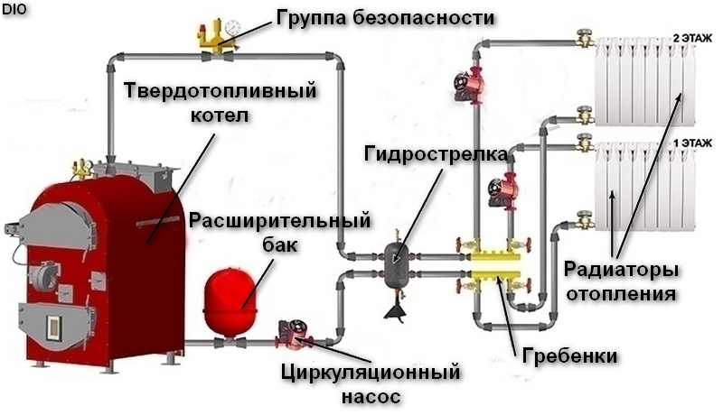
It differs from collectors in that it can be connected to the hydraulic arrow at different heights. This directly affects the temperature of the coolant, and with it the temperature of each heating element in the house. Thus, using a harness with a hydraulic arrow, you can create an optimal thermal regime for each device separately.
Connecting a solid fuel boiler with heat accumulator
For equipment operating on solid fuel, it is recommended to install heat accumulator. It is a buffer tank for accumulating and then storing the heat generated by the boiler.
A very profitable device, because it allows you to increase the efficiency of solid fuel equipment and at the same time save heating material.

The wiring diagram for a solid fuel boiler with a buffer tank is as follows. Inlet and outlet pipes heat generator are connected to the heat accumulator, and from it to the heating elements. Now two contours are formed at once:
- between the heat buffer and the boiler;
- between the buffer and the heating devices of the house.
As the coolant passes through the heating system, it fills the buffer tank. In this case, cooled liquid from the heating elements passes below, and hot liquid from the boiler passes above. The buffer accumulates heat when the firebox is operating at full power. After the fuel burns out, the accumulated heat from the tank is released through the heating system for a certain period of time. After the storage buffer, a pump and a three-way valve are installed to adjust the temperature of the heating fluid.
The wiring diagram of a solid fuel boiler with a battery tank saves fuel, allowing you to add coal and firewood much less frequently. It must be taken into account that with such piping, the boiler power should be sufficient for heating and warming up the buffer tank.
Wiring a solid fuel and gas boiler (electric boiler)
This harness is relevant and in demand among residents of country houses. It allows you to organize year-round comfort in the house, including several heating sources in the overall system. As a rule, steam from a gas heating boiler with a solid fuel device is installed, as well as solid fuel equipment with an electric boiler.
 Solid fuel boiler+electric
 The wiring diagram for gas and electric devices with wood is the same, is quite simple because it uses heat accumulator at the same time and as a hydraulic gun. This allows you to efficiently supply heat to a large number of heating points at once (radiators, heated floors, boiler, heated towel rail, etc.). In this case, the heat from the gas heating boiler (electric) and wood-burning boiler charges the buffer tank, and then it supplies thermal energy to the heating end points.
There is also another option for connecting a gas heating boiler (electric boiler) and a solid fuel boiler together, without using a buffer tank, because it is quite expensive. Here the main source of heating is a wood-burning boiler, with a gas boiler as an auxiliary one.
Operating principle. After solid fuel burns out, the air temperature decreases. This detects the sensor installed in the room and immediately starts the gas boiler. When the main boiler cools down, it switches off automatically. The gas one operates until the wood-burning unit begins to process the next portion of fuel. Now, in reverse order, the room temperature sensor turns off the gas heating device.
The scheme with such a harness is simple, you can install it yourself.
Piping with connection of an indirect water heater
The wiring diagram for a solid fuel boiler with a boiler is quite common due to its cost-effectiveness and efficient operation. This is especially relevant during the heating season, when you can save a significant amount on electricity.
This piping is designed in such a way that the heated liquid is supplied simultaneously to the boiler and radiators. In this case, the boiler circuit is connected to the heat exchanger of the water heater, which heats the water indirectly.
Heating a country house with a diesel boiler. Briefly about the important How to make a solar water heater for your home with your own hands? Choosing wood stoves for baths and saunas: firebox, power, heater Wood stove for a country house: choosing heating options
A heating boiler operating on various types of solid fuel differs in operation from gas and electric boilers. Here there are heating and cooling cycles associated with loading firewood, the danger of overheating of the coolant and low-temperature corrosion. Accordingly, the connection diagram of a solid fuel boiler to the heating system of a building has its own characteristics. The purpose of this article is to show how to correctly connect the unit to the heating system, including in conjunction with other boiler installations.
Basic wiring diagram for a solid fuel boiler
For a better understanding of the processes that occur during operation of the heat generator, we will show its wiring in the figure, and then analyze the purpose of each element. In the case when the heating unit is the only heat source in the house, it is recommended to use the following basic diagram to connect it:
Note. The basic diagram, where there is a small boiler circuit and a three-way valve, shown in the figure, is mandatory for use when working together with other types of heat generators.
So, the first thing on the path of coolant movement from the boiler installation is the safety group. It consists of three parts installed on one manifold:
- pressure gauge - to control the pressure in the network;
- automatic air release valve;
- safety valve.
When operating a solid fuel boiler, there is always a risk of overheating of the coolant, especially at modes close to maximum power. This is due to a certain inertia of fuel combustion, because when the required water temperature is reached or there is a sudden power outage, it will not be possible to immediately stop the process. Within a few minutes after the air supply stops, the coolant will still heat up, at which point there is a risk of steam formation. This leads to an increase in pressure in the network and the danger of destruction of the boiler or burst pipes.
To avoid emergency situations, the piping of a solid fuel boiler must include. It is adjusted to a certain critical pressure, whose value is indicated in the heat generator’s passport. As a rule, the value of this pressure in most systems is 3 Bar; when it is reached, the valve opens, releasing steam and excess water.
Further, in accordance with the diagram, for proper operation of the unit it is necessary to organize a small coolant circulation circuit. Its task is to prevent cold water from the home heating system from entering the heat exchanger and water jacket of the boiler. This is possible in 2 cases:
- when starting heating;
- When the pump stops due to a power outage, the water in the pipelines cools down, and then the voltage supply is restored.
Important! A power outage situation poses a particular danger to cast iron heat exchangers. A sudden supply of cold water from the system by the pump can lead to its cracking and loss of tightness.
If the firebox and heat exchanger are made of steel, then connecting the solid fuel boiler to the heating system through a three-way valve protects them from low-temperature corrosion. The phenomenon occurs when condensation forms on the inner walls of the combustion chamber due to temperature differences. Mixing with volatile fractions and ash, moisture forms a layer of scale on steel walls, which is very difficult to clean off. In this case, the metal is subject to corrosion and the service life of the product as a whole is reduced.
The scheme works on the following principle: while the water in the boiler jacket and in the system is cold, the three-way valve allows it to circulate through a small circuit. After reaching a temperature of 60 ºС, the unit begins to mix coolant from the network at the inlet of the unit, gradually increasing its flow rate. Thus, all the water in the pipes warms up gradually and evenly.
Circuit with heat accumulator
A number of European Union countries have introduced rules according to which schemes for connecting solid fuel boilers to the heating system must necessarily include a heat accumulator. Without it, the operation of such heaters is simply prohibited. The reason is the high content of carbon monoxide (CO) in emissions while limiting the supply of oxygen to the firebox to reduce the intensity of combustion.
With normal air access, harmless carbon dioxide (CO2) is formed, so the firebox must operate at full capacity, transferring energy to the heat accumulator. Then the CO content will not exceed environmental standards. In the post-Soviet space there are no such requirements yet; accordingly, we continue to block air access in order to achieve slow smoldering of wood, for example, in.
Heat accumulators are commercially available as a finished product, although many craftsmen make them themselves. By and large, this is a tank covered with a layer of thermal insulation. The factory version may have a built-in DHW circuit and heating element for heating water. This solution allows you to accumulate heat from a wood-burning boiler, and when it is idle, provide heating for the house for some time. The connection diagram of the boiler with the heat accumulator is shown in the figure:

Note. In the circuit, instead of a mixing unit consisting of several elements, a ready-made device is installed that performs the same functions - LADDOMAT 21.
Connection with an electric or gas boiler
Often, homeowners purchase a solid fuel boiler as the main source of heat, leaving the existing gas or electric unit in reserve. Usually it looks like this: while the owner of the house is awake, he devotes time to the wood-burning heat generator, and at night a different type of heater is turned on. It would be a sin not to connect these two boilers in such a way that the system works automatically, that is, when the firewood in the firebox dies out, the electric heater comes into play.
Of course, the most effective way to work will be a parallel connection of a gas and solid fuel boiler through a buffer tank. The latter will simultaneously perform 2 functions: serve as a hydraulic separator and a heat accumulator.

While all heating systems operate from a heat generator using wood or coal, the gas boiler is in standby mode. But when the fuel in the chamber burns out, the temperature of the water in the buffer tank will begin to decrease. This will automatically start the burner of the gas unit, since its circulation pump is constantly running. It will deliver the cooled water to the temperature sensor, which will start the main burner through the controller. When the firebox is ignited, the reverse process will follow; the gas burner will turn off due to the high temperature of the coolant.
It should be noted that the connection diagram for a solid fuel boiler with an electric boiler through a buffer tank will be absolutely identical. But it has a significant drawback - high cost. This heating system arrangement is relevant for large private houses; for small buildings there are simpler solutions:

Both boiler systems are switched on in parallel, with check valves installed at the outlet of each. Since the pump in an electric boiler is built-in, runs constantly and cannot be turned off, you need to choose the right pump for a solid fuel heat generator. The pressure of the latter must be higher so that when working together it has priority over the electric boiler.
This connection of an electric boiler to a solid fuel boiler will function automatically if two devices are installed:
- thermostat that controls the operation of the biomass heat generator pump;
- room temperature sensor that controls the electric boiler.
While burning wood, the room sensor will record the normal temperature in the house, so the electric heater will not turn on. But as soon as the fuel burns out, the air in the room will begin to cool, as will the coolant in the pipes. When the water temperature drops, the pump thermostat will turn it off, and the sensor will turn on the electric heat generator. More detailed information can be obtained by watching the video:
Conclusion
So, the design of a heating system with a solid fuel boiler should ensure its correct, and most importantly, safe operation. At the same time, it is necessary to provide for all individual installation conditions and link the basic circuit to the location, preferably with the recommendations of specialists.