Ordering sliding gates is very expensive, especially if you do it in a small town. There are not many specialists here and, in the absence of competition, they often significantly inflate the prices for their services. A big city also has its own difficulties - if you turn to a company with low prices, there will be doubts about their qualifications and the quality of the final result. And the higher cost of the structure itself and its installation now, unfortunately, is not a guarantee of good quality.
Diagrams and drawings of sliding gates without automation
A properly designed and manufactured gate should open with virtually no effort. A good roller system, together with well-calculated weight distribution throughout the structure, results in smooth and easy movement of the gate along the guide beam. Let us consider, as an example, a diagram that describes all the necessary elements and components for sliding gates.
- Steel pillars made of profiled pipe with dimensions 100x100 and a height of 4 meters in a concrete base
- Metal pillars are installed in concrete pillars made using TISE technology (with an expanding base at the bottom)
- A concrete foundation strip poured over the pillars and containing approximately one and a half cubic meters of concrete.
- Right wheel group
- Left wheel group
- Upper wheel group for securing the canvas and additional fall protection
- Metal frame made of profiled pipe (60x40 or 40x25) with a wall thickness of 2 to 4 mm
- Frame for the gate, made of square pipe 100x100 mm and wall thickness 3 mm. Attached to the pole with long bolts at the level of the top and bottom edges
- Wicket frame made of profiled pipe. The cross-section of the pipes is the same as that of the gate frame
- Ground level (asphalt, paving stones)
- A long channel is welded to the bottom beam of the door frame
- Electric drive (optional)
- Toothed rack for clutching the flywheel of the electric drive
- Location of the counterweight. Its weight is calculated based on the dimensions of the gate base.
- Platforms for roller groups fixed in a concrete foundation using mortgages
- Fence made of profile pipe 60x40 or 40x25
- Large and strong hinges
- Hinges for gates. Must also be very durable
This diagram shows the complete set of necessary parts for creating sliding gates. They can operate either with an automatic drive or open manually, without an electric motor.
One of the most technologically complex elements is the roller base. Most often, if you have the opportunity and resources to make sliding gates with your own hands, then the rollers are not made independently. The durability of the structure and ease of use will largely depend on their strength and reliability. But good videos can only be made if you have sufficiently high skills in working with a lathe.
Therefore, the wheelbase for sliding gates is usually purchased separately. Its cost is around 10,000 rubles. This price includes a set of guide beam (from 5 to 7 m), supports with 8 rollers on a metal base, end roller, lower and upper gate catchers, square bracket and nylon roller. The assembled device can support gates weighing up to 500 kg. The photo below shows the Roltek Eco 6 kit as an example.

If you have the skill to accurately process metal parts on a machine, then you can make the rollers yourself. An example of a finished wheelbase with drawings of rollers, which was made by a professional turner, can be seen in the photo below.


When designing a specific gate, it is important to correctly calculate the dimensions of all frame parts so that it does not deform under its own weight during operation. Particular attention should be paid to the dimensions of the counterweight side, which will balance the main part of the frame visible from the outside. The aspect ratios are illustrated in the following diagram.

An example of a well-designed sliding gate with the exact dimensions of the opening and gate is shown in the diagram below.

If you look at the structure from above, the arrangement of elements will look like this.

The set of fittings that will be required to connect the gate base into a single system includes the following parts.

Depending on the design of a particular gate model, the list of elements may be larger or smaller. There are also options for creating suspended sliding gates. In such designs, the frame moves on rollers mounted on top. They move in the upper horizontal guide. The disadvantages of this option are that the top crossbar limits the height of vehicles that can pass under it. Next, we will consider the method of manufacturing and installing simple sliding gates based on a factory roller base.
Step-by-step instructions for making sliding gates
There are many ways to make sliding gates with your own hands. The technology proposed below is one of the options for carrying out work, which even a not very experienced master can do. To work with metal, you will definitely need a grinder and a welding machine. The rest of the tools are a list of those necessary for pouring the foundation, drilling and painting the frame.
The first step is to make mortgages. They will be laid in the foundation and will become supports for attaching the roller base. A channel 16 cm wide is cut into pieces 40-45 cm long. Then, reinforcement bars with a diameter of 10 mm are welded to it from the inside.

Next, a hole is dug for the foundation, about 60 cm wide, 2 meters long and 1.8 m deep. Formwork 30 cm high is made from several rows of boards on top. To protect the concrete, the entire pit is covered with glassine, which is fixed to the formwork on top using a construction stapler.


The mortgages are installed into the pit immediately, and the upper plane of the channel should be at the same level as the finished concrete foundation. To achieve this, the mortgages can be tied to a horizontal crossbar, which rests on the formwork. The final level of concrete should be slightly below the upper limit of the formwork. It is also important to adjust the pillars in level and set them at the same height. Each is 3 meters long.


While the base dries, you can begin welding the gate frame. The weight of the structure is quite large, and it will bear high loads, so a profile pipe with a cross-section of 60x40 mm will be required. First, the perimeter was assembled in such a way that if you lay it on the ground, the pipes would stand on an edge, that is, on an edge with a smaller cross-section (40 mm).

Then sheets of corrugated sheets are laid out on the frame in order to determine where to place the vertical posts. The verticals and all internal jumpers are welded flat, that is, in this position of the frame, as in the photo, the pipes will lie with the larger edge on the ground. This way, the internal elements are attached flush to one side of the frame, leaving a small space on the other (note the areas highlighted in red).

A pipe with a cross section of 40x20 mm is welded into these empty spaces around the entire perimeter. It will serve as an additional base for attaching corrugated sheets.

As for the sequence, after manufacturing the verticals, the central horizontal cross member is installed. Lastly, all the jibs are welded, previously cut at the desired angle using a grinder.
A guide beam with a groove in the lower part is welded to the bottom edge of the frame (included with ROLTEK Eco 6 rollers). This is the guide of the future gate in which the wheelbase will move.

When the entire structure is completely welded, you need to clean it from rust, if any. Carrying out the work may take some time, and even if the pipe was initially purchased without rust, then during its exposure to the open air, rust may form on it. The voids are sealed with acrylic sealant to prevent moisture from entering the frame. After which you can start painting it.

The movement of the frame will be carried out along rollers, which must be securely fixed to the foundation. To do this, channel No. 20 is welded to the surface of the metal mortgages embedded in the foundation through 63 mm corners.


You also need to make frame travel limiters on the tops of the pillars. They are welded to the posts from above, and on the front side of the gate they are additionally attached using an angle.


The pillars, base channel and stops are also painted with acrylic paint. Now you can install the frame in its place.

The frame of the gate is made from a 50x25 mm profile pipe with an additional internal perimeter from the same pipe for fastening the profiled sheet. A separate rectangle is provided for installing a lock. For convenience, the dimensions of the door are taken equal to the size of the corrugated sheet, approximately 1.8x1.15 m.

The gate requires its own external frame, which is welded from a 60x40 mm pipe. First, the racks are attached to the gate using clamps, after which all marking, cutting and welding of the structure is performed. At the same stage, hinges are welded onto the frame and gate.


A separate foundation needs to be dug to install the gate. Additional, deeper holes are dug under the pillars using a drill.

Channel No. 16 is welded to the left post of the wicket frame. It will include a gate frame.

Gate catchers, which come complete with rollers, are welded to the channel from below and above.

To install a lock in a gate, you will need to make two restrictor plates - an internal one and an external one. The outer one is welded to the frame, and the inner one is fixed with bolts.


Now all that remains is to remove the outer fence and cover the wicket and gate with corrugated sheeting.

All you need for this is the appropriate tools and the ability to understand drawings and diagrams. With some diligence, the finished result will look and function no worse than a factory-made design. Such gates can be successfully manufactured and installed at the dacha, in a country house, in a parking lot, etc.
As you already understand, we are talking about cantilever-type gates, the panel of which moves on roller supports. There is another design option - rail, which is considered obsolete today, and we will not consider it. And for those who are interested in a cantilever (sliding) structure, we offer detailed instructions for its installation, which includes a set of works on preparing the gate opening, laying out the foundation and the installation sequence.
DIY sliding gates, concrete base or piles
Video on how to make sliding gates with your own hands
Sliding gate device
- The guide is integral with the gate leaf and takes the entire load from its weight;
- Roller support (trolley) – 2 pieces, the gates in the console part are installed on them;
- The end roller is removable - serves as a support for the edge of the gate when closed;
- Lower catcher – takes the load from the support roller when the gate is closed;
- Upper catcher – reduces the windage of the gate when closed;
- Bracket (upper clamp with rollers) – holds the sash against lateral swings;
- Stand – supports are mounted on it to ensure movement of the gate leaf.
The process of manufacturing and installing sliding gates with your own hands involves constructing a foundation. A guide beam is welded to the lower edge of the sash, the load from which is taken by two roller supports installed on the foundation. It is thanks to them that the gate leaf moves in the desired direction.
The support rollers are located inside the supporting console. Gates of this design can be automatic (operated by an electric drive) or opened manually. They are very convenient to use at any time of the year.
Gate leaf requirements
In order for the structure to remain stable and rigid during strong winds, its sash must be sufficiently rigid to withstand wind loads.
Also, the canvas should not sag under its own weight.
It is better to purchase high-quality metal for the gate leaf, without signs of corrosion, and in satisfactory condition. The total required amount of metal and reinforcement can be calculated from the drawings.

Gate drawings

From different manufacturers you can find many different models of sliding gates. It is not difficult to find their drawings, if desired, including on the Internet. We offer you the best, in our opinion, option from a technical and financial point of view.
The gate leaf is made of a metal pipe. The frame will require a profile pipe 60x40x2 mm; for lathing – 20x20x1.5 mm. We suggest using a drawing with which you can make a frame for sliding gates with an opening width of 4 m.
After the frame is ready, a guide beam should be welded to it, which can be purchased ready-made from our company, which sells components for do-it-yourself sliding gates. After this, the frame is primed and painted in the desired color with metal paint.
A- opening width; B- guide length (opening width + 40%); Pipe - 60x40 mm.(main frame); Pipe - 20x20 mm.(lathing);
Gate painting
The first step is to prepare surfaces for painting and degrease them. For this purpose, you need to clean the surfaces with sandpaper or treat them with a grinder and a grinding disc. Cleaned areas should be wiped with acetone. You can start priming.
The primer must be applied evenly to the surface, avoiding streaks and drops whenever possible. After the primer layer has completely dried, the paint layer is applied. Such a thorough approach will ensure that the paint will lie smoothly and the structure itself will not be subject to corrosion.
The second paint layer is applied after the first has completely dried. If the result is not very aesthetic, you can paint it a third time. The time for complete drying may vary depending on the time of year and range from several hours to 2-5 days. Once painting is complete, you can proceed to further steps.


Selection of components
The selection criteria in this case are the width of the opening, the height of the gate leaf, and their total weight. The main element of the gate, on which its reliability and performance depends, is the guide.
The key to efficiency when installing sliding gates with your own hands is the correct selection of components, which are present in our catalog in the form of ready-made kits:
- Russian – Roltek and Doorhan
- Italian – Came
- Belarusian – Alutech
The selection of components should be carried out taking into account the following requirements: The total length of the gate leaf is calculated using the formula “opening width + 40%”. The components are selected according to the length of the guide beam and the permissible load.

Calculation example
For example, the width of the opening is 3.8 m. Therefore, the length of the gate leaf will be equal to 3.8 m + 40%, i.e. 5.32 m. In this case, you can buy a standard set with a 6 m guide. Usually, when the opening width does not exceed 4 m, ready-made sets of components are purchased, designed for a load of up to 500 kg. The guide beam in them has a cross-section of 71x65 mm and a wall thickness of 3.5 mm.
If the opening width exceeds 5 m, a set of components designed for more severe loads exceeding 600 kg is required. In such cases, before purchasing a ready-made set, it makes sense to consult with the company’s specialists for the optimal choice.
Installation of sliding gates
Having a certain understanding of the design of gates and the features of their installation, you can carry out independent installation. The movement of the canvas occurs from the inside of the site, along the fence (fence). Therefore, first of all, you need to take care of the place where the sash will roll back so that there are no obstacles in its path.
We suggest you consider the option of rolling the canvas to the right. The distance required to roll back the gate leaf is equal to the width of the opening plus the size of the cantilever part, which, in turn, is about half the width of the opening. If this requirement is met, the process of opening and closing the gate will not cause problems. The cantilever part itself does not close the opening, but acts as a counterweight.
Sequence of work
- Foundation construction: pit development, soil excavation, installation of a foundation element, concreting;
- Cabling arrangement (if it is planned to install automatic gates);
- Installation of gates and return posts;
- Automation installation, gate testing.
Construction of a concrete foundation
1st stage
In order to mark the hole for the foundation, you need to set aside a distance equal to ½ the width of the passage in the direction the gate rolls away, along the fence of the site, starting from the edge of the gate opening. This will be the location for our concrete base (length). Step back approximately half a meter from the fence towards the site - this will be its width. Thus, we will have the perimeter of the future foundation.
In some cases, fence posts can be used as support posts for sliding gates. If this is not possible, a counter post must be provided. The hole for it is located on the opposite side of the opening, strictly opposite the hole for the foundation. This is done taking into account that the return post adjoins the fence from the inside and does not reduce the width of the opening.
If you plan to make automatic sliding gates with your own hands, it is necessary to provide conditions for laying the electrical cable under the driveway. You will need a plastic or metal pipe with a diameter of at least 25 mm.
2nd stage
Excavation is usually carried out to a depth of at least 2 m, i.e. exceeding the freezing depth. As for the Moscow region, where the freezing depth is less, it is enough to remove the soil from the hole under the foundation at a depth of 1.7-1.8 m.
3rd stage
In order to make an embedded element, you will need a section of channel 16, along the length of the hole for the concrete foundation. The reinforcing grid and ties can be made from reinforcement d 12. The sequence of actions is as follows: first, sections of reinforcement are welded to the channel, then transverse ties (see image).

4th stage
The finished embedded element is placed in the hole with the reinforcement down, so as to ensure a tight fit of the side surface of the channel to the fence post. You should use a level to make sure that the body of the channel is fixed in a strictly horizontal position, parallel to the gate opening line.
Important point
The height of the top of the embedded element in relation to the plane of the road surface. If they are located at the same level, then the minimum gap between the road and the bottom edge of the gate will be about 100 mm. Using the adjustment pads, you can slightly increase this gap. But it is not possible to reduce it without compromising the manufacturability of the fastening.

If the standard gap size of 100 mm is not suitable for some reason, a deeper installation of the embedded element is required.
When it is planned to install fixed sliding gates with an opening width of more than 4.5 m, two support pillars will be needed in order to ensure stable operation of the gate and its ability to withstand windage during opening and closing. Also, in some cases, existing fence posts cannot be used as supports for sliding gates.
In such cases, you will need to prepare one or two support pillars, the size of which is calculated as the height from the foundation to the top point of the gate plus 50 mm. The finished structures are installed in the pit and connected in the lower part with the embedded element (see figure).

5th stage
Concreting for DIY sliding gates performed after the final installation of the embedded element. The pit is filled with concrete mortar so that the level of concrete is higher than the surface of the embedded element. The hardening time is at least six days.
1st stage
Marking the line of movement of the sash is carried out as follows. A cord is pulled along the line of the gate opening, 2-3 cm short of the return post. This will be the trajectory of the sash movement. The cord should be pulled at a height of 15-20 cm.

2nd stage
The figure shows how to fix the adjustment pads on the trolley platform.

3rd stage
Now it is necessary to determine the extreme positions of the first and second roller bearings. Step back 150 mm from the edge of the opening along the plane of the embedded element and draw a line for the extreme position of the first trolley. Draw the tangent of the second trolley as follows: measure the length of the gate together with the console part and set aside this length, minus 100 mm, from the edge of the counter post along the plane of the embedded element. We obtain the extreme position of the second cart.
4th stage
The gate is assembled as follows. Insert the roller supports one by one into the supporting profile, placing them in the center. Bring the gate to a vertical position, move both supports to their tangents, and install the gate close to the cord.

5th stage
Actually, we are installing it. The adjustment pads of the second trolley must be welded, after which the sash must be completely rolled out into the opening and its position must be finally adjusted. After this, weld the adjustment pads of the second cart.
- Remove the canvas from the roller carts;
- Remove the trolleys themselves from the adjustment platforms;
- Weld the platforms to the embedded element;
- Attach roller carts to them;
- Push the sliding gate leaf onto the roller trolleys;
- Close the gate;
- Use a wrench to make final adjustments to the gate position.

6th stage
To ensure that the roller carriages are installed correctly inside the supporting profile, you need to perform the following steps. Loosen the top nuts securing the trolleys to the platforms and roll the gate back and forth several times, from one extreme position to the other. After making sure that the gate moves freely, you should tighten the nuts and make sure that the quality of the gate movement remains at the proper level.
If you find that the web is moving with difficulty, it is necessary to slightly loosen the fasteners and correct the distortions of the roller carts, especially in the plane perpendicular to the movement of the web.
7th stage
At this stage you need to install the end roller. We insert it inside the supporting profile and tighten the fastening bolts. We weld the end roller cover to the profile so that the roller reliably plays the role of an end stop during manual movement of the door leaf. The welding point in this case will be a more reliable fastening than a bolted connection.
The support profile plug is installed on the inside of the gate and welded in place. This element is needed to prevent snow from getting inside the supporting profile in winter. Otherwise, the snow will be rolled away by the rollers of the trolley, and this may lead to jamming of the gate. When installing DIY sliding gates this point must be taken into account.

8th stage
Now you need to install the upper clamp with rollers. To do this, loosen the fasteners of the rollers and install the bracket above the gate leaf so that its side with the holes is directed towards the support post, and the rollers grip the top of the gate leaf.
Press the bracket against the post and secure it. Bring the gate to a vertical position, aligning it with a level, and secure it with the rollers of the upper lock.

9th stage
If you plan to sheathe the sliding gate leaf, you can use, for example, a profiled sheet for these purposes, having previously ordered it cut to the required dimensions. Installation of the profiled sheet should be carried out from the front edge of the door leaf. Attaching it to the gate frame can be done in two ways: using self-tapping screws or by riveting, however, the second method is more reliable.
The second sheet is mounted overlapping with the first (overlaid on one wave and secured). Thus, it is necessary to install the required number of profiled sheets until the door leaf is completely covered. The last sheet will most likely have to be trimmed further in order for it to fit within the perimeter.
10th stage
After the gate trim is completed, you can begin installing the catchers - upper and lower. Since the role of the lower catcher is to reduce the load on the roller carts when the gate is closed, it is installed when the gate is fully loaded. With the gate completely closed, you need to bring the lower catcher under the end roller so that the supporting plane of the catcher is above the level of the end roller.
The upper catcher is installed in such a way that when the gate is closed, its upper brackets touch the protective corners of the front edge of the gate leaf.

Stage 11
On DIY sliding gates you can install automation. In this case, the movement of the sash will be carried out using an electric drive. For this purpose, a toothed rack is attached to the door leaf - a universal part that is compatible with electric drives for gates of all manufacturers. Such a rail is usually included in the kit of fasteners.
The gate automation kit usually comes with installation instructions, which you should follow.
Automation selection
Automation for sliding gates – more freedom, more comfort!
Don't want to manually open and close your sliding gate?
A remote controlled drive will allow you to do this without leaving the car.
Tools and equipment
To manufacture and install sliding gates you will need:
- Welding machine, preferably an inverter one. It does not damage the metal and ensures optimal weld quality.
- Grinder with discs of various types. With its help you can cut metal blanks for gates.
- An air compressor that will ensure uniform painting of the gate. If it is not available, you can paint the gate with a regular roller.
- Pliers, hammer, drill, tape measure, level, riveter.
If you have any questions regarding the installation of sliding gates, or would like to find out the cost of installation services, please contact us by phone.
Get the manual for free!
Get a consultation for free!
Sliding or sliding gates are a complex mechanism, but nevertheless, due to their convenience, they have become quite widely used both at industrial facilities and in private households. There are a lot of manufacturers who make ready-made gates and components for them; qualified labor will quickly and competently carry out the installation, but those who want to save money and apply creative energy in business will be interested in installing sliding gates with their own hands. Moreover, this is quite possible.
Types of sliding gates
Sliding gates come in different designs, each of which has its own advantages and disadvantages. Let's mark them.
Hanging sliding gates
These gates were most often used at the entrances of enterprises and other protected areas. At a considerable height, so that cargo transport could enter, a metal beam was mounted, and no longer Not The gate leaf was suspended using roller trolleys.
 Hanging gates - reliable, but material-intensive
 This design is quite reliable, and such gates, created more than 50 years ago, still work, but are now rarely used for two reasons:
- The upper beam still limits the dimensions of the gate opening.
- This design is very material-intensive and what was allowed during the Soviet era at the then metal prices is simply unacceptable now.
Sliding gates on rails
This is the simplest design of sliding gates and theoretically the most reliable. The door leaf, standing on rollers, rides on a special rail located on the surface. The gate is still supported at one upper point in the place where the gate goes when opened. Such gates are best used where the territory is periodically and constantly cleaned, which is often unattainable under Russian conditions. Normal snowfall will easily block the operation of such gates, and it can be very difficult to get them to work again.

A significant advantage of such gates is that to open they need to go beyond the fence exactly the width of the opening, and this, in conditions of limited space, can be a determining factor for making a decision in favor of such a design.
Cantilever sliding gates
In order for the gates to have no size restrictions at the top and to avoid contact with the ground rail, cantilever sliding (sliding) gates were invented. This is the most complex gate design, but these “sacrifices” are absolutely justified. The leaf of such gates does not have contact with the surface, but is suspended on cantilever roller blocks using a guide beam. Most often, such a beam and roller blocks are located at the bottom of the gate.

There are cases when the guide beam and roller blocks can be located in the middle or even on top of the door leaf. This may be justified when the cantilever units can be hung on the main wall of the building or there are any building structures or structures that can withstand the loads from the door leaf. Otherwise, you will have to specially construct a power structure for the gate, which is not always profitable.

That is why in most cases, cantilever sliding gates with a lower support beam are used.
Prices for sliding gates
Sliding gates
Description of the design and operation of cantilever gates
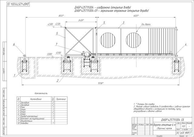
A schematic diagram of a sliding gate with a lower console position can be seen in the figure.

The door leaf is mounted on a frame (1) made of a profile metal pipe. A supporting beam (2) is welded to the frame, which has a special profile, into which the roller carriages (3) fit tightly. In this case, the beam can move together with the gate left and right along the carriages, ensuring the opening and closing of the gate. Obviously, the beam and roller carriages bear the greatest load, especially when they close or fully open the gate. In order to unload the gate when completely closed, an end unloading roller (4) is used, which enters and rests against the lower catcher (5). In another part of the gate, to fix the door leaf when fully open, they can also use an end roller with a catch stop, but it is not visible in this diagram.
To ensure that the gate does not have lateral swings, there is a guide with rollers (7) and an upper catcher (6), which fixes the door in the closed state. To prevent dirt and foreign objects from getting into the inside of the beam, plugs (8) are used. The entire gate structure is mounted on three main power elements: a support post (9), a counter post (10) and a foundation for roller carriages (11). If the site already has sufficiently strong gate supports (brick, concrete or metal), then they can be used as support and response posts, and if not, then they will have to be built separately from a profile metal pipe. In any case, the foundation for the console will have to be built separately.
In sliding gates, an electric drive is quite easily implemented, which is fixed between the roller carriages. To set the blade in motion, a toothed rack is attached to its side surface. The drive is equipped with a control unit, as well as various safety devices.

Advantages of cantilever sliding gates
Cantilever-type sliding gates have a number of advantages:
- Such gates do not have detachable leaves and therefore do not reduce the usable area of the territory, and if the gate is accidentally opened, there is no danger of damaging the vehicle standing in front of it.
- The gate opening has no lower or upper restrictions on dimensions.
- Abundant ones do not interfere with the operation of the cantilever gates, since the leaf is hung at a distance of about 10 cm above the ground surface.
- All rolling elements that ensure the operation of the gate are located inside the beam, and therefore are not affected by weather factors. Even a child can set the gate in motion, thanks to its thoughtful design and low friction.
- The powerful foundation of the console and a well-thought-out system for holding the door leaf in a vertical position allow such doors to withstand heavy wind loads.
- Sliding gates are easiest to equip with an electric drive and safety elements.
Sliding gates still have disadvantages, but they are few:
- Cantilever sliding gates are one of the most complex in design, which is why their installation is not easy.
- To install them, it is necessary to have a free section of the fence one and a half times larger than the size of the opening, which is not always achievable.
Determining the feasibility of installing sliding gates
Even with the great desire and remarkable financial capabilities of the site owner to install sliding gates, situations may arise when installation is either impossible or very difficult. What are these situations?
- The space where the gate will roll back along the fence should be free by at least one and a half width of the gate opening. This is explained by the fact that on the door leaf, in addition to the part covering the opening, there is also a technological part, which in length occupies at least half of the width of the opening - this way the loads from the gate will be better distributed on the cantilever block.

- Sliding gates move in a straight line, which means that the required area of free fence space must also be straight.
- In the place where the gate will move there should be no uneven terrain that would interfere with the free movement of the gate.

- There should be no gates in the path of the gate; it is better to make them on the opposite side. Sometimes sliding gates with built-in wickets are ordered, but they will inevitably have high thresholds, which is extremely inconvenient for children and the elderly.
- It happens that the owners intend to use the gate as a wicket - when the canvas moves away to a distance sufficient for people to pass through. This is not necessary, since any gate mechanism is designed for a certain number of cycles and frequent use of them will greatly reduce the service life.
- If you enter the site from a narrow lane, then to make maneuvering easier, you need to increase the gate opening, which will affect the dimensions of the doorway.

If there are no such difficult situations on the site, then you can start installing sliding gates with your own hands.
In order for sliding gates to be installed correctly and have a long service life in the future, the technological process must be divided into several stages.
Preparatory work
The first and one of the main parts of the preparatory operations is assessing the location of the gate installation. What should you pay attention to?
- If the gate is installed to replace the old one, which has a different design, then the presence and condition of the support pillars will be assessed. If they are made of brick, reinforced concrete section at least 20 per 20 cm, profile metal pipe cross-section at least 60 per 40 cm, their strict verticality is maintained, and they are securely fixed in the ground, then they can well serve as a support and response post for sliding gates. If not, you will have to rebuild your pillars.
- Near the support pillar it should be possible to dig a hole for the foundation, which should be located close to the pillar, run parallel to the fence and have dimensions of 500 mm by 2000 mm.
- If there is a new fence on the site, then all work on its construction and preparation for the installation of sliding gates can be combined, which is most preferable.
- Very often, brick pillars are erected at the entrance to the territory, which is both practical and beautiful. When constructing them, you need to make embedded elements in the form of steel plates 100*100 mm and 5 mm thick, three on each pillar. The top plate must be placed on the inside of the post close to the edge that is closer to the opening. The distance from the top of the column to the plate is 200 mm. The lower embedded plate is located similarly to the upper one, but at a distance of 200 mm from the zero mark. “Zero” is considered to be the level of entry through the gate. The middle plate is placed midway between the top and bottom. Gate elements will subsequently be attached to them.

- When building a new fence, you can take into account that most often the width of the passage for sliding gates is 4 meters. This standard has long been adopted in European countries. All manufacturers of components and fittings have the necessary sets of elements specifically for this size of gate. To make your work much easier, it is better to use a ready-made solution.
- It is necessary to decide what the door leaf will be and what it will be lined with. There are a lot of options, and in each of them the gate will have a different weight. This may influence the selection of the required strength elements. Most often, corrugated sheeting has been used lately, but there are options for cladding with wooden lining, forged decorative elements, or simply leaving a lattice structure made of steel pipes.

- Before purchasing the necessary components, you need to draw up your own detailed drawing with specifications or use ready-made solutions that are available in the albums of gate manufacturers and on the forums of country house owners on the Internet. In any case, you need to be very clear about the design of how many materials you will need and which ones.
Marking work
When the gate posts are installed, regardless of whether the fence is erected or not, you can begin marking. To do this you need:
- Determine the level of the zero mark, which is taken to be the surface level at the entrance to the garage opening. Moreover, it is not at all necessary that the entrance surface will already be ready when work begins. This can be done later. This level must be marked on one pillar and then transferred to another using a water or laser level.
- At the level of the zero marks, the cord is pulled close to the inner surface of the pillars, and the cord must pass beyond the support table (the one where the gate will move when opened) to a distance of at least two meters. The horizontality of the tensioned cord is checked.
Sliding gate foundation installation
In order to absorb the loads from the weight of the gate at rest and when moving, you need to build a foundation. To do this, a channel No. 20 with a length of 2000 mm is needed as the upper part on which the roller units and electric drive will be mounted. For the foundation it is necessary to dig a hole, which is adjacent to the support pillar, has a length of 2100 mm, a width of 500 mm. The depth is determined by the level of soil freezing in winter. In most regions, a depth of 1500 mm will be sufficient.

To reinforce the foundation and create a connection between the channel and the foundation, three square-section frames with a side of 150 mm from reinforcement No. 16 and a length of 1400 mm are welded. For cross braces, you can use reinforcement No. 10-12 with a pitch of 300-400 mm.
The finished frames are welded to the lower surface of the channel in the middle of its flange. The center lines of the outer frames are located 400 mm from the edges of the channel, and the third – exactly in the middle. After this, you need to add 10 cm of sand or sand-gravel mixture to the bottom of the hole, compact it and begin installing the finished channel with reinforcement cages. In this case, you should take into account:
- The channel is laid close to the supporting post, strictly parallel to the line of movement of the gate, flush with the zero mark. A previously stretched cord will help to do this.
- To prevent laitance from leaking into the ground from the concrete mixture, which reduces the strength of concrete, it is better to line the bottom and walls of the pit with plastic film.
- The surface of the channel should be at the zero level, therefore, when installing frames with a channel, it is good to use pieces of reinforcement that can be used to fix the structure in the pit. When supplying concrete, a significant load will be applied to the frames, so the fixation must be reliable.
- To make it easier to level the upper part of the concrete with the channel, it is very convenient to install edged boards on top with the surface at zero level.

- If you plan to use an electric drive with an automation unit and a security system, then you should immediately take care of laying the necessary cables. The laying diagram can be seen in the figure. Cables should be laid either in a corrugated pipe, or better yet, in a polyethylene pipe with a diameter of 20 mm.

It's time for concrete work. To fill the foundation of sliding cantilever gates, you must use concrete of a grade of at least M250-M300. To prepare it you will need components in the following proportions by volume:
- One bucket of M400 cement.
- Two buckets of washed sand.
- Four buckets of crushed stone or gravel.
- The amount of water depends on the moisture content of sand and cement and ranges from 0.7 to 1 bucket. The use of plasticizers reduces the amount of water required and increases the mobility of the mixture, which is useful during installation.
The amount needed for the foundation will, of course, be greater, the main thing is to maintain the specified proportions. To prepare the concrete mixture, it is best to use a concrete mixer or a powerful construction mixer. When mixing manually, the quality of concrete deteriorates.
 A concrete mixer is an indispensable assistant for constructing a gate foundation
 First, sand and cement are poured into the concrete mixer. After mixing them, add some water to mix the solution until smooth. Next, crushed stone or gravel is added and water is gradually added until the concrete becomes homogeneous and mobile. When laying concrete in a hole you must:
- Feed the concrete mixture gradually so as not to move the leveled structure.
- After laying the next portion of concrete, you need to pierce it in several places with a reinforcement bar to remove possible air bubbles.
- After laying and leveling the top layer, wipe the surface of the channel with a wet rag so that it remains clean for subsequent operations.
Complete maturation of the concrete occurs within 28 days, but after a week it will already gain the strength that will allow installation of the gate. And at this time you can do other technological operations.
Manufacturing of sliding gates
When making gate leaves, if you do not have sufficient skills in welding metals, it is better to go where specialists in a workshop will make them to the required dimensions. Sliding gates are a fairly large structure and at home it will be difficult to ensure that all parts are located in the same plane, which is extremely necessary. Another advantage of making gates in workshops is that priming and painting can be done with a compressor, and this gives a better quality finish. But if you still want to do everything yourself, then this is quite possible.
One of the possible door leaf options is shown in the figure. The main frame is made from a 60*40 mm profile pipe, and the stiffeners and internal filling are made from a 20*40 mm pipe. The supporting beam, which is located at the bottom of the drawing, has a length of 6 meters and it must be welded to the gate, so it is time to purchase a set of components for sliding cantilever gates and profile pipes for making the door leaf.

A wide range of accessories for sliding gates is presented in various stores and construction markets. It is available both from a Russian manufacturer and imported. When purchasing fittings, you need to take into account the weight of the future door leaf and the size of the opening. In our case, the size of the opening is 4000 mm, and the weight of the canvas, if covered with corrugated sheeting, will be up to 400 kg, which must be reported to the seller.
The standard gate kit includes:

- The guide beam is 71*60*3.5 mm, 6 meters long.
- Two roller bearings.
- End roller.
- Lower end roller catcher.
- Upper catcher.
- Guide device with two rollers.
- Two plugs for the beam.
To weld the gate, you will need to make an assembly table consisting of three stands of the same height. The supports can be stakes driven into the ground at the same level and boards laid on top. The main thing is that all three stands lie in the same horizontal plane.
Another option for an improvised assembly table can be timber or building stones laid on the ground and placed at one level.

A profile pipe purchased at a metal warehouse rarely does not have pockets of corrosion, so before making the gate, all pipes should be thoroughly cleaned of rust stains and contaminants. The most convenient way to do this is with a grinder and a special grinding disc.

According to the drawing, 60*40 mm profile pipes are cut for the main gate frame. In this case, you must try to make sure that during welding there are no holes left for access to the internal cavity of the pipe. Marking should be done with a tape measure and a square, and cutting should be done with a grinder with a cutting disc, or better yet, with a cutting machine that allows you to accurately observe all the angles.
Pipes are laid out on the mounting surface, guided by the drawing, compliance with dimensions and perpendicularity is checked, and then all seams are tacked sequentially. After checking the dimensions and plane, all pipe connections are welded with a continuous seam. All remaining open ends of the pipes are welded with plugs. After this, all welding seams are carefully cleaned with a grinder and a grinding disc.

Profile pipes 40*20 mm for stiffening ribs are cut to size, which are then applied to the inner surface of the main frame, tightened with clamps and pinched pointwise. This is how the entire internal frame is assembled. After checking compliance with the dimensions in the drawing, checking the diagonals of the rectangular part of the gate, the plane of the structure, all seams are welded. At the connections of the pipes of the internal frame, continuous seams are applied to each other, and to connect the side surfaces of the main frame with the inner one, seams of 10-15 mm are made with an interval of 400-500 mm. Welding must be done in a checkerboard pattern so that excessive overheating in one place does not cause the entire structure to “deteriorate.”
A guide beam is welded to the bottom surface of the gate. To do this, it is fastened with clamps, the correspondence of the axes of the gate leaf and the beam is checked, and then welded with seams of 30-40 mm every 400-500 mm. After this, all seams are cleaned with a grinder.
For priming and painting, the gate must be installed in a position close to vertical. It is best to use an automotive anti-corrosion primer, which must be applied in two layers. It is preferable to do this with a compressor and sprayer, but you can also use a brush, but it will take longer and the quality of the coating will be worse. Particular attention should be paid to pouring primer into the gap between the beam and the gate. It would also be appropriate to cover this gap with “sausages” of acrylic sealant. After this, the entire gate can be painted in two layers. Under no circumstances should the inner surface of the load-bearing beam be painted!

After the paint has completely dried, you can install cladding on the gate, the most preferred of which is corrugated sheeting, as it combines light weight, strength, beautiful appearance and a reasonable price.
Installation of sliding gates
The installation of a cantilever structure on a previously installed channel can begin no earlier than 7 days after concreting. To mount roller carts, it is recommended to purchase a mounting plate with studs, which will allow you to:
- Adjust the gate position in height and horizontality.
- It is easy to remove the gate for repairs or replacement of roller blocks.

To install the gate you need:
- Place the roller carriages onto the mounting plate, making the height the same and average on all studs. Do not tighten the upper nuts too much.
- The position of the mounting plates must be marked on the foundation. To do this, measure 150 mm from the edge of the channel that is closer to the opening and draw a line perpendicular to its length. This will be tangent to the edge of the first mounting plate.
- To find the position of the second support, you need to measure the total length of the gate and subtract 100 mm from it. The resulting distance must be set aside from the beginning of the return post parallel to the goal line to the channel. At this point a perpendicular is drawn, which will be tangent to the second mounting plate.
- If the load-bearing capacity of the pillars is good and the anchor bolts will be fastened in them well, then the use of additional metal pillars is not necessary. If not, then a profile pipe with a height equal to the height of the gate plus 200 mm, with a cross-section of 40 * 40 * 2 mm, is welded vertically using the previously prepared mortgages. On the support post it can be welded close to the edge, and on the return post it can be welded at a distance of 20-50 mm from the edge of the post.

- At a height of 150-200 mm at a distance of 20-30 mm from the branch and supporting pillars, a cord is stretched horizontally, parallel to the line of movement of the gate. It will indicate the position of the tangent to the edge of the supporting beam. The cord must be stretched throughout the entire movement of the gate: from the edge of the table to the position of the edge of the gate when it is fully open.
- Roller carriages are placed in the supporting beam and moved approximately to the middle of the gate. Then, with the participation of assistants, the door leaf is placed vertically above the channel. The roller carriages are moved along previously marked lines, and the stretched cord should touch the guide beam along its entire length. This position can be fixed using stands made of planks. After checking the verticality, the roller platforms can be “grabbed” by electric welding in several places.
- The movement of the gate is checked, its verticality and horizontality, which is checked in the closed position. If necessary, correction is made using adjusting nuts on the studs of the platforms. The gate should move easily along the guide, parallel (lightly touching) the tensioned cord. The gaps between the support and response posts should be the same, and from the zero mark to the bottom edge 80-100 mm. If everything is normal, then the carriage fastening nuts can be tightened and the platforms themselves can be welded in a circle.

- A plug is mounted on the rear console part of the load-bearing beam. An end roller is mounted in the front part of the beam. Each manufacturer has its own installation method, so you must use the instructions.
- A guide device with two rollers is mounted on the support column in its upper part. To do this, a bracket for attaching the guide is attached to the pole, and holes are marked. In brick or concrete it is necessary to fasten with anchors with studs with a diameter of 10 mm, and in metal - with appropriate self-tapping screws. If welding will be used for fastening, it is better to temporarily remove the plastic rollers. After mounting on the post, the rollers are positioned so that they tightly cover the door leaf, maintain its verticality and do not interfere with the smooth movement.

- The gate is rolled out to the fully closed position, and the location for attaching the lower catcher is marked on the return post. The end roller should fit tightly onto the catcher shelf, partially relieving the load on the roller blocks. The catcher is mounted using appropriate fasteners and the movement of the gate and the ease of its fixation in the closed position are checked.

- An upper catcher is installed, which prevents the gate from swinging in the wind. In a completely closed state, the position of the catcher is outlined and its fastening is made. Very often, the upper catcher in the kit also has a protective bracket that is put on the door leaf, which protects against damage to the coating. The bracket is mounted so that when closing it is the one that enters the catcher.

- If necessary, a rear limiter is installed to prevent the gate from rolling back far when fully opened.
After proper installation, the gate should move very easily and be fixed in its extreme positions. The final work will be cleaning all welds, covering them with anti-corrosion primer and painting. Next, handles for opening and closing can be attached to the gate leaf, and also installed. Each drive manufacturer has its own installation features, which are described in detail in the accompanying documentation. But this work will be much easier, since the main thing has already been done - installing sliding gates with your own hands.
Video - Installation instructions for sliding gates
Video - Installation of a ready-made gate kit without welding
Video - How to make sliding gates yourself
Previously, sliding gates were installed only at industrial facilities and enterprises, but over time, the ease of use of such structures has brought them well-deserved popularity in private households. Their mechanism is not as simple as that of conventional gates, so most owners prefer to order production and installation from specialized companies, however, if desired, they can do all the work themselves. You can learn about how to make sliding gates with your own hands, as well as about their varieties, assembly and installation stages from our article.
Forged sliding gates
What is this – a sliding gate?
Let's figure out what sliding gates are, what they are like and what their differences and advantages are. Gates of this type consist of a door leaf mounted on rails made of a metal profile, which smoothly moves along guides using special rollers. The mechanism saves space, is automated and operates thanks to an electric motor with a power of 40-100 W. Depending on the type of fastening, there are sliding gates on a rail, cantilever gates and hinged gates. Let's look at each of the structures in more detail.
Mounted
Such gates are usually installed at the entrance to the territory of industrial enterprises. Their design ensures the movement of the web along the upper beam using roller carts, and the height of the opening allows the passage of freight vehicles. Recently, hanging gates, despite their reliability and long service life, are used less and less due to the significant cost of metal for their construction.

Console
This type of gate does not have an upper beam limiting the opening, and moves on roller blocks along a console, which is located at the top, bottom or in the middle of the door leaf. The bottom-mounted design is easier to implement, since the other two options require the construction of additional supports.
 Gates with a console located in the middle
 Sliding on rail
The sliding design, which moves along the bottom rail on rollers, is reliable, but not very practical. If debris, snow, or ice freezes on the rail, it can temporarily disable the gate. Therefore, if you do not plan to constantly clean the area around the gate or live in an area with a harsh climate (heavy snowfalls, long winters), it is better to choose a cantilever opening mechanism.
 Mechanism with bottom rail
 Choosing material
Making sliding gates with your own hands will require the use of the following materials and components:
- pipes for the frame with a rectangular section 60x30 mm and 40x20 mm;
- sheathing material (corrugated sheet, board, lining, polycarbonate);
- metal or concrete supports;
- U-shaped channel No. 20;
- reinforcing rod with a diameter of 12 mm and concrete mixture;
- electric motor;
- rack;
- set of accessories and fasteners;
- set for electrical wiring (wires, cables, protective pipes).
The material is purchased after drawing up a drawing and calculating the dimensions of the gate. It is not recommended to make fittings yourself; you can buy everything you need in hardware stores and showrooms that deal with door structures.
 Required components
 When choosing, pay attention to the quality of metal guides. They must have the correct shape, smooth edges and a wall thickness of at least 4 mm. Check how the roller moves inside the guide. To avoid problems with opening in the future, it is preferable to take parts with a smooth motion. It is very important that the channel and rack match the length of the door leaf, taking into account the counterweight.
Automation is selected based on the approximate weight of the structure. Also important are the wind loads acting on the gate, which depend on the height of the leaf and the material from which it is made. Taking into account the increased loads due to icing and snow placed on the engine in the winter, it is advisable to purchase models with power reserves. For example, for sliding gates weighing about 400 kg, an electric drive designed for a weight of 800 kg is suitable.
Sliding gate diagram
When drawing up a design drawing, you should correctly calculate the height and length of the gate, as well as the dimensions of the counterweight (the tail part located outside the opening). The height should correspond to the fence, the length should correspond to the width of the opening, the tail should be made approximately half as long as the gate leaf.
 Recommended parameters for sliding gates with an opening of 4 m
 At the same stage, the type of frame is determined. It can consist of a frame and 2-3 sections of rectangular pipes fixed at an angle or a frequent sheathing of horizontal and vertical guides. If desired, such gates can have a built-in gate, but this requires the purchase of additional materials - profiles for the frame, hangers and other fittings. In addition, the threshold of such a gate will be high, and this will create inconvenience for children and the elderly.
We build sliding gates
Since sliding gates with a top suspension and mechanisms moving along a rail are not very convenient for use in private homes, we will consider the stages of construction using the example of a cantilever structure with a bottom fastening. Work begins with an inspection of the site.
It is necessary to make sure that there is free space around the gate for rolling back the canvas, and that the terrain is sufficiently level. If old gates are being replaced, they are inspected, assessing the condition of the supports. It is not necessary to demolish and replace strong pillars with new ones; they can be used for a sliding structure. Next comes the turn of excavation work.
Foundation and guides
The base for the gate is placed along the fence (from the site side) in the direction of its opening. Under the foundation you will need to dig a trench 50 cm wide and 1.5-2 m deep, depending on the level of soil freezing. At the same time, holes are dug for the supports if they could not be preserved from the previous structure.
 Scheme of concreting and installation of guides
 A cushion of carefully compacted sand and gravel is poured onto the bottom of the trench. Then, a frame for the foundation is welded from the reinforcement, and a channel is welded on top of it. This will become the bottom part of the gate to which the motor and roller assemblies will be attached.
The frame is placed inside the pit so that the channel is located close to the support pillars and is flush with the ground surface. To prevent concrete from spreading, formwork made of boards is installed along the edges of the trench. It is advisable to immediately take care of the power supply to the engine and, at the stage of laying the foundation, lay the wiring in protective polyethylene pipes.
The trench is concreted with a mixture of cement, sand and crushed stone in a ratio of 1:2:4, water is added depending on the moisture content of the sand, until a creamy consistency is formed. It is recommended to use a concrete mixer for mixing.
 Foundation formwork
 The finished solution is poured into the pit gradually, trying not to disturb the position of the reinforcing frame. After pouring, the foundation is pierced in several places with a reinforcement rod to allow excess air to escape. It takes about a month for the base to completely harden, but you can begin further installation work within a week.
Installing gate posts
The installation of sliding gates does not require the use of powerful supports; usually metal or concrete pillars with a diameter of 10 cm are sufficient. They are installed at a distance equal to the opening, buried at least 1 m into the ground, leveled and filled with concrete. It is better to do this simultaneously with preparing the trench for the foundation.
Along with metal ones, brick supports are also popular. To construct them, a pipe or channel is installed in the center of the planned pillar using the method described above and pieces of reinforcement (mortgages) are welded to it in the places where the components of the gate mechanism will be located. Then, the support is covered with brick so that the reinforcement remains outside. Subsequently, structural parts are attached to it.
 Structure of a brick support
 Fastening the main elements
When assembling a sliding gate structure with your own hands, first connect all the mechanical parts, and then connect the electrical ones. First of all, roller carriages are attached to the mortgages, along which the web moves. On the opposite post, at the top, and sometimes at the bottom, so-called traps are welded (lightly at first), ensuring smooth closing of the gate. The installation process will be described in more detail below.
 Location of main elements
 Preparing the moving section
An important stage of work is the construction of the section frame, consisting of a frame and a counterweight. To do this, you will need to select a flat area of sufficient size to accommodate the entire structure.
Previously purchased pipes with a rectangular cross-section are inspected for corrosion and, if necessary, polished. Markings are applied to them and the necessary parts are cut out with a grinder. Then, checking them with the drawing, they are laid out on a flat surface and lightly secured by welding. The resulting structure is checked for dimensional conformity and absence of distortions, and the frame parts are welded together using a continuous seam. Stiffeners are made in the same way. At the bottom of the section, a guide profile and a gear rack are attached.
 Frame construction
 The finished frame is treated with a sanding attachment; it is also recommended to prime and paint it. To do this, the frame is installed vertically and coated with an automotive primer using a sprayer, and after drying, paint is applied in two layers.
Section covering
After waiting for the painted frame to dry, you can move on to the sheathing. Typically, inexpensive and practical corrugated sheeting is used as a cladding material, but it is possible to use boards or polycarbonate. The selected material is attached to the frame with bolts or self-tapping screws every 20-30 cm, after marking it and drilling holes for fasteners.
Section installation
The installation of sliding gates with your own hands is completed by securing the section to the poles and connecting the automation. You can start installing the gate no earlier than a week after concreting the foundation and supports.
Installation sequence:
- Roller carts are welded to the channel laid on the foundation; the rollers are placed inside the guide at the bottom of the web.
- The gate is checked with a building level and its upper part is fixed with a bracket.
- The movement of the gate is checked and, if everything is in order, the roller carriages are firmly welded.
- An end roller is attached to the front of the section from below.
- The gate is closed and the coincidence with the catchers on the support is checked; if necessary, their position is adjusted.
After assembly, the welding areas are treated with an anti-corrosion primer and the electric motor is connected in accordance with the documentation supplied with it. The structure is ready and if you take proper care of it, remembering to periodically clean and lubricate the rollers, it will last for many years.
 Connecting automation - the final stage
 We hope our instructions on how to make sliding gates yourself will be useful to you. But remember, before you start work, you should draw up a draft of the future design and discuss it with a specialist. Good luck!
A good, reliable fence with a beautiful gate not only protects a suburban area from uninvited guests, but also gives a clear idea of its boundaries. To make the fence more convenient and practical, its gates are equipped with devices that simplify their opening and make this process automatic. One of the most popular designs is a system with a mechanism that allows you to move the fence to the side. Today, many companies are engaged in installing sliding gates, but we suggest making them yourself.
Design and principle of operation of sliding gates
Depending on the type and location of the supporting surface, sliding gates are divided into rail and roller, but since the latter have a more reliable design, systems with a bottom rail guide are practically not used today. As for the mechanism with support rollers, it is not difficult to assemble it yourself, since all components can be purchased at a retail chain or made independently.
The previously popular sliding gates with a bottom guide rail have today been replaced by a more reliable design with support rollers
This gate can be built in two ways:
- monoscreen,
- double synchronous design.
A monoscreen is a structure of one leaf, which rests on roller guides (carts or cantilever supports) installed on the side of the opening. The gates move along them to one side, opening up space for cars to pass through. This system does not require an upper banner between the pillars and is used when the height of the canvas is no more than 2 meters. The simplicity and convenience of a monoscreen contribute to its popularity for arranging private areas, open areas and courtyards.
Roller sliding gate diagram
Double synchronous gates have a pair of leaves that slide in opposite directions. Unlike a monoscreen, the structure has two supporting foundations and an upper beam, which serves as a guide for additional rollers. The cantilever system is capable of supporting increased weight of the leaf, therefore it is used for gates with a height of more than 2 meters. It is a good option for equipping garages for trucks and high hangars, various warehouses, industrial facilities, etc.
Since the need to install high gates in a private courtyard rarely arises, we will further consider single systems. Among other things, such sliding gates have a simplified design, so they are more suitable for making them yourself.
Roller trolleys are the main supporting elements of the structure
In addition to the guide and roller supports (cantilever blocks or trolleys), several other elements ensure the operability of the structure.
- Lower and upper catcher. They are U-shaped brackets installed on the edges of a catching post (support, rack) and designed to fix the gate in a closed state. The upper catcher prevents the sash from falling to one side, while the lower lock, in addition to this function, also relieves the load on the rollers and guide.
Catchers are made of thick metal, because the reliability of fixing the gate in the closed position depends on them
- Support rail or bracket (roller stop). It is installed along the upper edge of the main post and serves for additional fixation of the canvas.
Support bracket assembly with rollers
- Support roller. Attached to the front end of the guide and serves as a plug, damper and support element. When the sash enters the lower catcher, it softens the blow and takes on part of the weight of the structure.
Support roller with rubber damping pad
In addition, some parts of the system are equipped with plugs that prevent snow accumulation and serve as decorative elements.
Design Features
Before you start purchasing materials, you should draw up at least a small drawing or sketch indicating the main dimensions and calculation of the required material.
Canvas dimensions
One of the main issues in gate design is determining the width and other dimensions of the structure. First of all, you should determine the distance between the gate posts, since all further calculations depend on this value. This takes into account:
- the size of vehicles that will enter the site;
- vehicle entry angle;
- free gap between the overall width of the car and the gate supports, which should be 0.3–0.5 m on each side.
For middle-class passenger cars, a gate with a width of 2.5–3 m will be sufficient, while a truck or tractor requires an opening of at least 3.5 meters.
Design and dimensions of the sliding gate leaf with a frame for a metal profile
If movement perpendicular to the fence line is difficult and entry at an angle is required, then this value must be increased by another 1.5 times. But we must also take into account the fact that for any reason (slippery surface, inexperienced driver, improperly secured load) the car may shift or tilt to the side. Therefore, the optimal gate width can be considered to be about 4.5 m - this will be enough for any situation.
When calculating the width of the canvas, add 20 cm to the size of the opening. This must be done so that when the gate is closed on the side of the support rollers, the yard is not visible through the gap. If this possibility was not taken into account during the manufacture of the sash, then you can get out of the situation by slightly moving the pillars towards each other. When determining the height of the gate, many believe that it should be the same as that of the fence, but usually the leaf is made a little smaller. This is due to the fact that the lower edge of the fence is installed with a minimum gap from the level of the site, while the sash does not touch the ground and is installed with a gap of about 10 cm.
Drawing of a sliding gate leaf without a frame for an infill profile
In fact, the distance between the lower guide and the level of the yard is adjusted using support platforms, which set the height of the roller carts. Depending on their position, the doors rise above the site to a height of 10 to 15 cm.
In addition, the height of the canvas is influenced by the dimensions of the frame of its frame and the width of the lower guide. In order for the gate to end up on the same level as the fence, when designing it is necessary to take into account all these nuances and make an accurate calculation.
Drawings and diagrams
The basis of the design of sliding gates is a guide that moves along cantilever blocks.
To prevent the support rollers from obstructing the passage, they are moved behind the side clearance. In this case, the sash is lengthened due to a special slope that acts as a counterweight. You can avoid distortion when closing sliding gates if the length of the slope is equal to ½ the width of the gate.
The entire load during operation of the mechanism is taken by the roller carts, so their installation requires a strong, reliable base. The foundation is made in the form of a massive reinforced concrete structure with an upper foundation platform made of a wide metal channel. In the future, it will be convenient to use not only for mounting roller bearings, but also for attaching the automation drive.
The recoil type has a very simple design. Understanding the operating mechanism is enough to independently draw up the necessary sketches and make calculations. Nevertheless, we present to your attention diagrams and design drawings that will serve as visual aids and help in the work. Among other things, you can take one of the finished projects as a basis for making sliding gates yourself.
Drawings for manufacturing
 Installation diagram for the manufacture of sliding gates
  Roller support drawing
  Drawing of a blade with a guide rail
  Support bracket drawing
  Installation diagram of the laying platform
  Block diagram of sliding gates
  End roller drawing
  Specification of sliding gate design details
  Drawing of a guide with a roller assembly
What you will need to build it yourself
When starting to build a gate, you need to have a set of components (accessories), which can be purchased as a set or made independently. As for tools, you don’t need any specific devices - everything you need can be found even by a novice home craftsman.
Selecting parts for the recoil mechanism
There are several options for components for sliding gates, depending on the width of the opening and the weight load:
- for gates weighing up to 400 kg and width no more than 4 m;
- for canvases weighing up to 600 kg and a width of no more than 6 m;
- for sashes weighing from 600 kg and width 6 m or more.
When choosing one or another set for your needs, you should definitely take into account the filling material of the leaf, because it has a significant impact on the weight of the sash.
The creation kit consists of the following parts:
- bottom guide;
- support bracket with rollers;
- roller support - 2 pcs.;
- roller platform support stand - 2 pcs.;
- support (end) roller;
- lower and upper catchers;
- plastic plugs.
The guide of the lower rollers must be rigid enough to maintain its original shape and not deform under wind load. To ensure this condition, responsible manufacturers make the rail from high-quality structural steel with a thickness of at least 3.6 mm - this parameter should be taken into account when choosing it.
Set of accessories for assembling sliding gates
Since the entire mass of the gate is supported by roller carriages, their bearings must be of high quality, and the rolling surfaces themselves must have high hardness. On sale you can find cantilever blocks with plastic rollers that reduce the noise level when the gate moves. Keep in mind that these parts will have to be replaced after some time, as even the highest quality thermoplastics are no match for case-hardened steel. Before installation, it is recommended to open the support roller bearings to check the amount of lubricant - this determines whether the gate will creak when moving, and how long these parts will work without play or jamming.
The sash is secured from above by a supporting bracket. To ensure the stability and reliability of the structure, its thickness must be at least 4 mm. As for the guides installed on it, rubber rollers have proven themselves to be the best. The load on them is not that great, but the fact that they do not scratch the gate frame during operation has a positive effect on the aesthetics of the structure.
When choosing a lower catcher, keep in mind that it works in tandem with a support roller. Be sure to check how freely the end switch fits into the latch. In addition, the end roller is designed to redistribute the load when the gate is closed, so the same requirements are imposed on it as on the main supporting elements of the system.
The metal plate from which the catchers are made must have a thickness of at least 4 mm, since the reliability of fixing the sash in the closed position depends on its quality. In addition, the strength of these parts must be ensured by the welding connection.
Any guide rail plugs will do. The main thing is that they prevent the ingress of snow and perform a decorative function.
The choice of material for lining depends entirely on personal preferences and financial capabilities, so you can use:
- corrugated sheeting, which is lightweight and easy to install using rivets or self-tapping screws. Profile panels can be selected according to thickness, color, depth and width of the wave, and their coating can protect the metal from corrosion for many years;
- steel sheets - selected by thickness and size. Most often used as a basis for forged gate elements;
- polycarbonate, with which the gate will be the lightest;
- picket fence or lining - they must be treated with antiseptic agents and coated with varnish or paint. Only in this case can you count on the durability and aesthetic appearance of lumber;
- forging - can be used either alone or in combination with polycarbonate, lumber or steel sheets. Today in the retail chain you can buy individual forged elements, from which, using welding, it is easy to build a real work of blacksmith art;
- panel (chocolate) - to obtain it, metal sheets are stamped. You can find “chocolate bars” of various sizes on sale. They are attached to the frame by welding or rivets.
When using forging, steel sheets or panels to cover the door, you should take into account the significant increase in the weight of the gate when choosing roller supports and other structural elements.
On sale you can find panels of various sizes, which allows you to create gates of original design
What tools and materials will be needed
The construction of sliding gates will require not only plumbing, but also concrete work, so you should prepare:
- shovel;
- crowbar or pickaxe;
- tamper;
- containers for bulk materials and concrete;
- welding machine;
- grinder (angle grinder or angle grinder);
- cutting and grinding wheel for angle grinders;
- hammer;
- screwdriver;
- set of open-end wrenches;
- roulette;
- scriber or pencil;
- a compressor with a spray bottle or brushes for painting.
If the sash trim will be made not of metal, but of wood, then you may need a circular or miter saw, a plane, a chisel and other carpentry tools.
Profile steel pipes are best suited for the manufacture of gate leaves.
In addition to components and cladding elements, you will need many other materials. So, to make a sliding gate for a 4-meter opening, you will need to bring to the site:
- at least 18 meters of profile pipe 50x50 mm or 60x40 mm with a wall of 2 mm - for welding the frame frame;
- up to 20 linear meters of pipe 40x20x2 mm, which will be needed for the internal parts of the frame;
- channel No. 20 with a length of at least 2 m - for the construction of an embedded support platform for roller guides;
Instead of a channel, you can use two pieces of steel angle with a flange 100 mm long, which are welded along the length. It is not recommended to install embeds only under the carriages of roller supports, as well as to concrete the studs - in this case it will be difficult to align the rollers and adjust the automatic closing device (drive). - thick sheet metal for flashings - mortgages, which are installed in the masonry during the construction of side supports (pillars);
- about 15 m of reinforcement or steel bar with a diameter of 10–12 mm, which will be needed for fastening the channel and constructing the foundation;
- sand, crushed stone and cement for preparing concrete.
You should take care in advance about the aesthetics of the structure, so to paint the frame or the entire canvas you will need paint and a primer. Any alkyd enamel for exterior use and primer for metal surfaces are suitable.
Step-by-step installation of sliding gates
The correct approach to the manufacture of sliding gates will allow you to obtain a strong, reliable design and avoid errors in operation. Therefore, it is better to divide the whole process into several stages:
- construction of support pillars;
- arrangement of the foundation;
- production of canvas and individual structural elements;
- installation of the structure.
To achieve success, everything must be done according to the work plan. Each step must be accompanied by control of geometry and other technological parameters. Only in this case can you count on the fact that even a child will be able to open the gate.
Installation of pillars
Installation of support pillars is one of the most critical stages, since in the future they will be responsible for the stability of the entire structure. Racks can be made from various materials - oak timber, solid metal, brick or concrete. It is recommended to concrete the pillars to a depth of at least 1 m, and in areas with high groundwater levels to build a common foundation for all structural elements of sliding gates.
Diagram of sliding gate support structures
If metal pipes are used for the racks, then installing the catchers and support rail does not cause difficulties - they can be secured by welding. In the case when the pillars are made of stone or brick, it is necessary to install mortgages in the masonry. These fasteners are metal platforms made of thick sheet steel, to which pieces of a metal rod or thick wire are welded. During the construction of pillars, flexible elements are laid in the seams, installing the strips at the required height.
So, to install the support posts, they dig a hole with a diameter of at least 0.5 m and a depth of more than 1 meter, into which the pillar is installed. Next, level it using a level and fill it with concrete. For reliability, several crossbars made from pieces of angle iron, pipes, fittings, etc. can be welded to the lower part of the metal rack.
Construction of the foundation
Before starting installation work, it is necessary to mark the foundation of the support platform and prepare a foundation pit for its arrangement. For these purposes, 0.5 m is retreated from the plane of the fence - this will be the width of the trench. The foundation should be 20–30 cm longer than the sash counterweight.
If automation is used to open the gate, then even at the stage of installing the pillars and constructing the foundation, electrical cables are laid in the ground. To protect them, a corrugated plastic casing is used.
A channel up to 20 cm wide is used as a foundation. Its length is equal to half the width of the opening plus an allowance of 10–20 cm for installing roller support platforms. To ensure the solidity of the mortgage, it is reinforced with a frame made of reinforcement.
Drawing of the foundation of the support platform
The foundation is built like this:
- dig a trench 1–1.5 m deep. On sandy soils, as well as with a high groundwater level, the bottom of the pit should be below the freezing point;
- rods are cut from a metal rod or reinforcement: long 1–1.5 m (according to the depth of the trench) and short 0.2 m. The latter will be needed half as much - they will be used as jumpers;
- long pieces of reinforcement are welded to the side shelves of the channel at a distance of 30 cm from each other, obtaining a structure similar to a bench with many legs;
- opposite rods are connected in pairs using 20-centimeter jumpers at a distance of 0.7–0.8 m from the channel;
- The embedded structure is lowered into the trench, leveling the channel to the height of the site.
The channel must be aligned strictly horizontally so that its upper plane coincides with the level of the roadway. If tiles, concrete or asphalt pavement is still being planned, then an increase in the height of the driveway must be taken into account.
- install formwork and armored belt;
- pour concrete and compact it thoroughly.
According to the technology, the foundation must stand for 28 days for the concrete to reach brand strength.
Arrangement of the foundation of the support platform
Making the sash
To manufacture the load-bearing frame of the gate leaf, profile metal pipes with a cross-section of at least 50x50 mm are used. In order not to get a sash that is driven by a “propeller”, it is necessary to arrange a platform with a strictly horizontal plane. To do this, choose a wide, flat place and lay wooden slats or bars on the ground with small gaps. Level control is carried out using a laser or bubble tool and a construction cord.
It is convenient to use wooden supports for welding the sliding gate leaf
The fabric is welded from the bottom up, laying individual structural elements on the prepared plane.
- An outer frame is made, which is the main frame of the sash. To do this, a frame pipe with a cross section of 50x50 mm or 60x40 mm is welded to the guide rail. After this, vertical pipes are attached to its upper plane, and the upper cross member and slope are mounted. The welding seam can be made with tacks 2 cm long every 0.5–0.6 m.
The frame is welded in a staggered manner. This will prevent overheating of individual areas and disruption of the flatness of the structure. - Elements of the filling frame are welded to the base of the frame, which will be needed to attach the corrugated sheeting and will make the structure more rigid. Internal bulkheads are made of 40x20 mm pipes.
- The welding areas are cleaned with an angle grinder, after which the structure is coated with a primer.
- Using a spray gun, apply two or three layers of alkyd paint.
- After the protective layer has dried, the canvas is sheathed with corrugated board. To fasten it, use self-tapping screws or rivets, holes for which are drilled with an electric drill.
The frame, which will be sheathed with corrugated sheets, wood or polycarbonate, must be painted before filling
If steel sheets or forging are used as filling, they are welded at the stage of constructing the frame, after which they are cleaned and only after that the gate is prepared for painting.
Assembly instructions
- Installation of sliding gates begins with markings. In order to indicate the trajectory of their movement, it is necessary to stretch a cord along the roadway. The gap between it and the road surface should be 150–200 mm, and the distance to the support pillar should be 70 mm (with a recommended thickness of the road surface of up to 70 mm). In the future, the cord will serve as the center line when installing cantilever supports
- Determine the installation location of the front roller carriage. The principle here is simple - the farther the supports are placed from each other, the less will be the load on the bearings. However, the set of support rollers closest to the roadway is installed not along the extreme dimensions of the post, but at a distance of 15 cm in the direction of rollback. This is done so that the rolling roller protruding from the sash does not protrude onto the roadway. To determine the extreme position of the rear console support, subtract 100 mm from the total length of the web (with counterweight). The resulting value is laid off from the receiving pole (on which the catchers will be mounted) - this point will be the outer boundary of the second cart.
Determining the installation locations of roller bearings
- The supporting platforms of the roller supports are aligned to the obtained points and secured by welding, after which the rollers are installed on the adjusting plates.
The roller bearings are mounted on the base plate by means of supporting platforms. This allows you to avoid overheating of the rollers during installation and to be able to align the guide “horizontally”
- The door leaf is placed in place by rolling the guide onto the rollers. The supports are checked for correct installation, after which the sash is removed and the trolleys themselves are dismantled.
- The adjustment plates are securely welded.
Before welding the support platforms and installing the trolleys in place, the door leaf is removed
- The roller supports and canvas are installed in place, after which the gate is fixed in the closed state.
- The building level is set in the same plane as the guide, after which the adjusting bolts of the supporting platforms are used to set the gate “to the horizon.”
Correct installation of the roller carriage (with a supporting platform) will allow you to easily adjust the level of the guide beam
- The knurling roller is installed inside the guide, after which it is secured with bolts and secured by welding for reliability.
Installation of the knurling roller
- Opposite the post closest to the roller carts, a roller limiter is installed on the upper edge of the web. The support rail is secured by welding, after which the gate is adjusted vertically.
The support rail bracket can be attached to the post by welding - the wide adjustment range of each roller allows you to easily align the door leaf vertically
- Install the lower catcher. To mark the location of its installation, the gate is fixed in the closed position, the catcher bracket is placed under the support roller and pressed until it touches completely. The catcher is secured with bolts so that its position relative to the roller can be adjusted in the future.
If you do everything correctly and carefully, you should end up with a design like this:
Video: how to install sliding gates with your own hands
How to equip them with automation
An automatic opening system can be installed on such gates only if they move easily and without jerking on the rollers. To do this you need to purchase:
- rack;
- electric drive;
- signal light;
- limit switches or photocells;
- remote control;
- Control block.
Today there is no need to buy components separately - ready-made automation kits can be found on sale. To install the system, you will need the same tools that were used in the manufacture and installation of the gate.
Automation kit for sliding gates
The electric drive is attached to the same embedded channel as the roller bearings. The work is carried out in stages.

For safety reasons, a signal lamp is installed on the outermost pole. After this, check the correctness of the electrical connections and turn on the power supply.
You can use a screwdriver or any electric motor with a gearbox as a sliding gate drive, and use an inexpensive car alarm for remote control.
Video: sliding gates with a drive made from a screwdriver
Although sliding gates require more financial investment than regular ones, the lion's share of costs can be saved if you make them yourself. Ease of use and comfort provided by the remote control system are combined with high reliability and the ability to save space on the site. Not a bad argument for a modern and functional design, right?
Thanks to my varied hobbies, I write on various topics, but my favorites are engineering, technology and construction. Perhaps because I know many nuances in these areas, not only theoretically, as a result of studying at a technical university and graduate school, but also from the practical side, since I try to do everything with my own hands.