GOST 2.311-68
INTERSTATE STANDARD
UNIFIED SYSTEM OF DESIGN DOCUMENTATION
IMAGE OF THREAD
Official publication
Standardinform
M ENGINEERING STATE STANDARD
Unified system of design documentation
IMAGE OF THREAD
Unified system for design documentation.
ISS 01.100.20
Date of introduction 01/01/71
1. This standard establishes the rules for depicting and applying thread designations on drawings of all industries and construction.
The standard corresponds to ST SEV 284-76.
2. The carving is depicted:
a) on the rod - with solid main lines along the outer diameter of the thread and solid thin lines - along the inner diameter.
In images obtained by projection onto a plane parallel to the axis of the rod, a continuous thin line along the internal diameter of the thread is drawn along the entire length of the thread without a runoff, and in views obtained by projection onto a plane perpendicular to the axis of the rod, an arc is drawn along the internal diameter of the thread, approximately equal to * 1 2 3/4 circles, open anywhere (Fig. 1,2);


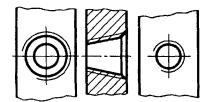
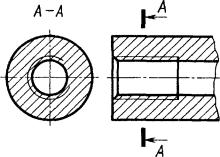
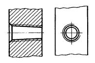
b) in the hole - with solid main lines along the internal diameter of the thread and solid thin lines - along the outer diameter.
On sections parallel to the axis of the hole, a continuous thin line along the outer diameter of the thread is drawn along the entire length of the thread without running, and on images obtained by projection onto a plane perpendicular to the axis of the hole, an arc approximately equal to 3/4 of the circle is drawn along the outer diameter of the thread, open anywhere (Fig. 3,4).


Official publication ★
Reproduction is prohibited
© Standardinform, 2007
When depicting a thread, a solid thin line is applied at a distance of at least 0.8 mm from the main line and no more than the thread pitch.
3. The thread, shown as invisible, is depicted with dashed lines of the same thickness along the outer and inner diameters (Fig. 5).
4. A line defining the thread boundary is drawn on the rod and in the threaded hole at the end of the full thread profile (before the start
escape). The thread boundary is drawn to the line of the outer diameter of the thread and is depicted as a solid main or dashed line if the thread is depicted as invisible (Fig. 6-8).
A-A

A-A

5. Hatching in sections and sections is carried out to the line of the outer diameter of the thread on the rods and to the line of the internal diameter in the hole, i.e. in both cases to a solid main line (see drawings 3, 4, 7, 8).
6. The length of the thread with a full profile (without run-out) on the rod and in the hole is indicated as shown in Fig. 9a and 10a.
The thread length (with run-out) is indicated as shown in Fig. 96 and 10b.
If it is necessary to indicate the amount of run-off on the rod, the dimensions are applied as shown in Fig. 9th century
The run of the thread is depicted as a solid thin straight line, as shown in Fig. 9b, c and 106.


An undercut of a thread made all the way is depicted as shown in Fig. Pies in. It is allowed to depict an undercut of the thread, as shown in Fig. 1\b and d.


7. The main plane of the conical thread on the rod, if necessary, is indicated by a thin solid line, as shown in Fig. 12.
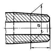
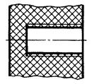
8. In drawings in which threads are not made, the end of a blind threaded hole may be depicted as shown in Fig. 13 and 14, even if there is a difference between the depth of the thread hole and the length of the thread.


9. Chamfers on a threaded rod and in a threaded hole that do not have a special structural purpose are not shown in projection onto a plane perpendicular to the axis of the rod or hole (Fig. 15-17). A solid thin line of the thread image on the rod should intersect the chamfer boundary line (see Fig. 15).


10. A thread with a non-standard profile is shown in one of the ways shown in Fig. 18, with all necessary dimensions and maximum deviations. In addition to the dimensions and maximum deviations of the thread, the drawing indicates additional data on the number of starts, the left direction of the thread, etc. with the addition of the word "Carving".

11. On the sections of a threaded connection in the image on a plane parallel to its axis, only the part of the thread that is not covered by the thread of the rod is shown in the hole (Fig. 19, 20).


12. Thread designations indicate, according to the relevant standards, the dimensions and maximum deviations of the threads and relate them for all threads, except conical and cylindrical pipe threads, to the outer diameter, as shown in Fig. 21, 22.


Designations for conical threads and cylindrical pipe threads are applied as shown in Fig. 23.
Note. The “*” sign marks the location where the thread designation is applied.
13. Special threads with a standard profile are abbreviated as C and the thread symbol.
(Changed edition, Amendment No. 1).
1. DEVELOPED AND INTRODUCED by the Committee of Standards, Measures and Measuring Instruments under the Council of Ministers of the USSR
2. APPROVED AND ENTERED INTO EFFECT by Resolution of the Committee of Standards, Measures and Measuring Instruments under the Council of Ministers of the USSR dated May 28, 1968 No. 755
3. The standard corresponds to ST SEV 284-76
4. INSTEAD GOST 3459-59
5. EDITION (August 2007) with Change No. 1, approved in April 1987 (IUS 7-87)


GOST 2.311-68
Group T52
INTERSTATE STANDARD
Unified system of design documentation IMAGE OF THREAD
Unified system for design documentation. Image of screw
ISS 01.100.20
Date of introduction 1971-01-01
INFORMATION DATA
1. DEVELOPED AND INTRODUCED by the Committee of Standards, Measures and Measuring Instruments under the Council of Ministers of the USSR
2. APPROVED AND ENTERED INTO EFFECT by Resolution of the Committee of Standards, Measures and Measuring Instruments under the Council of Ministers of the USSR dated May 28, 1968 N 755
3. The standard complies with ST SEV 284-76
4. INSTEAD GOST 3459-59
5. EDITION (August 2007) with Amendment No. 1, approved in April 1987 (ICS 7-87)
1. This standard establishes the rules for depicting and applying thread designations on drawings of all industries and construction.
The standard corresponds to ST SEV 284-76.
2. The carving is depicted:
a) on the rod - with solid main lines along the outer diameter of the thread and solid thin lines - along the inner diameter.
In images obtained by projection onto a plane parallel to the axis of the rod, a continuous thin line along the internal diameter of the thread is drawn along the entire length of the thread without a runoff, and in views obtained by projection onto a plane perpendicular to the axis of the rod, along
an arc approximately equal to a circle is drawn to the inner diameter of the thread, open anywhere (Fig. 1, 2);
b) in the hole - with solid main lines along the internal diameter of the thread and solid thin lines - along the outer diameter.
On sections parallel to the axis of the hole, a continuous thin line along the outer diameter of the thread is drawn along the entire length of the thread without running, and on images obtained by projection onto a plane perpendicular to the axis of the hole, an arc is drawn along the outer diameter of the thread,
approximately equal to a circle, open anywhere (Fig. 3, 4).
When depicting a thread, a solid thin line is applied at a distance of at least 0.8 mm from the main line and no more than the thread pitch.
3. The thread, shown as invisible, is depicted with dashed lines of the same thickness along the outer and inner diameters (Fig. 5).
4. The line defining the thread boundary is drawn on the rod and in the threaded hole at the end of the full thread profile (before the start of the run). The thread boundary is drawn to the line of the outer diameter of the thread and is depicted as a solid main or dashed line if the thread is depicted as invisible (Fig. 6-8).

5. Hatching in sections and sections is carried out to the line of the outer diameter of the thread on the rods
And to the line of the internal diameter in the hole, i.e. in both cases up to the solid main line
(see drawings 3, 4, 7, 8).
6. The size of the thread length with a full profile (without run-out) on the rod and in the hole is indicated as shown in Figures 9a and 10a.
The size of the thread length (with run-off) is indicated as shown in Figures 9b and 10b.
If it is necessary to indicate the amount of run-off on the rod, the dimensions are applied as shown in Fig. 9c.
The thread run-out is depicted as a solid thin straight line, as shown in Fig. 9b, c and 10b.

An undercut of a thread made all the way is shown as shown in Fig. 11a and c.
It is allowed to depict an undercut of the thread, as shown in Fig. 11b and d.
7. The main plane of the conical thread on the rod, if necessary, is indicated by a thin solid line, as shown in Figure 12.
8. In drawings in which threads are not made, the end of a blind threaded hole may be depicted as shown in Figures 13 and 14, even if there is a difference between the depth of the thread hole and the length of the thread.
9. Chamfers on a threaded rod and in a threaded hole that do not have a special structural purpose are not shown in projection onto a plane perpendicular to the axis of the rod or hole (Fig. 15-17). A solid thin line depicting the thread on the rod should intersect the chamfer boundary line (see Fig. 15).

10. A thread with a non-standard profile is shown in one of the ways shown in Figure 18, with all the necessary dimensions and maximum deviations. In addition to the dimensions and maximum deviations of the thread, the drawing indicates additional data on the number of starts, the left direction of the thread, etc. with the addition of the word "Carving".
11. On the sections of a threaded connection in the image on a plane parallel to its axis, only the part of the thread that is not covered by the thread of the rod is shown in the hole (Fig. 19, 20).

12. Thread designations indicate, according to the relevant standards, the dimensions and maximum deviations of the threads and relate them for all threads, except conical and cylindrical pipe threads, to the outer diameter, as shown in Fig. 21, 22.

Designations for conical threads and cylindrical pipe threads are applied as shown in Fig. 23.
Note. The "*" sign marks the location where the thread designation is applied.
13. Special threads with a standard profile are abbreviated as Sp and a thread symbol.
(Changed edition, Amendment No. 1).
The electronic text of the document was prepared by Kodeks JSC and verified against: official publication
Unified system of design documentation: Sat. GOST. - M.: Standartinform, 2007
GOST 2.311-68* “ESKD. Image of carving"
GOST 2.311-68
INTERSTATE STANDARD
UNIFIED SYSTEM OF DESIGN DOCUMENTATION
IMAGE OF THREAD
IPC PUBLISHING HOUSE OF STANDARDS
Moscow
INTERSTATE STANDARD
|
Unified system of design documentation IMAGETHREADS Unified system for design documentation. |
GOST |
Date of introduction 01.01.71
1. This standard establishes the rules for depicting and applying thread designations on drawings of all industries and construction.
The standard corresponds to ST SEV 284-76.
2. The carving is depicted:
a) on the rod - with solid main lines along the outer diameter of the thread and solid thin lines - along the inner diameter.
In images obtained by projection onto a plane parallel to the axis of the rod, a continuous thin line along the internal diameter of the thread is drawn along the entire length of the thread without a runoff, and in views obtained by projection onto a plane perpendicular to the axis of the rod, an arc is drawn along the internal diameter of the thread, approximately equal to 3/4 of a circle, open anywhere (Fig. , );
Crap. 1

Crap. 2
b) in the hole - with solid main lines along the internal diameter of the thread and solid thin lines - along the outer diameter.
On sections parallel to the axis of the hole, a continuous thin line along the outer diameter of the thread is drawn along the entire length of the thread without running, and on images obtained by projection onto a plane perpendicular to the axis of the hole, an arc approximately equal to 3/4 of the circle is drawn along the outer diameter of the thread, open anywhere (damn. , ).

Crap. 3
Crap. 4
When depicting a thread, a solid thin line is applied at a distance of at least 0.8 mm from the main line and no more than the thread pitch.
3. A thread shown as invisible is depicted with dashed lines of the same thickness along the outer and inner diameters (Fig. ).

Crap. 5
4. The line defining the thread boundary is drawn on the rod and in the threaded hole at the end of the full thread profile (before the start of the run). The thread boundary is drawn to the line of the outer diameter of the thread and is depicted as a solid main line or a dashed line if the thread is depicted as invisible (drawing -).

Crap. 6
Crap. 7

Crap. 8
5. Hatching in sections and sections is carried out to the line of the outer diameter of the thread on the rods and to the line of the internal diameter in the hole, i.e. in both cases to the solid main line (see drawing , , , ).
6. The length of the thread with a full profile (without run-out) on the rod and in the hole is indicated as shown in Fig. A and damn. A.
The thread length (with run-out) is indicated as shown in Fig. b and damn. b.
If it is necessary to indicate the amount of run-off on the rod, the dimensions are applied as shown in Fig. V.
The run of the thread is depicted as a solid thin straight line, as shown in Fig. b, V and damn. b.

Crap. 9

Crap. 10
An undercut of a thread made all the way is depicted as shown in Fig. A And V.
It is allowed to depict an undercut of the thread, as shown in Fig. b And G.

Crap. eleven
(Changed edition, Amendment No. 1).
7. The main plane of the conical thread on the rod, if necessary, is indicated by a thin solid line, as shown in Fig. .
Crap. 12
8. In drawings in which threads are not made, the end of a blind threaded hole may be depicted as shown in Fig. and, even if there is a difference between the depth of the thread hole and the length of the thread.

Crap. 13

Crap. 14
9. Chamfers on a threaded rod and in a threaded hole that do not have a special structural purpose are not shown in projection onto a plane perpendicular to the axis of the rod or hole (Fig. -). A solid thin line depicting the thread on the rod should intersect the chamfer boundary line (see drawing).
Crap. 15

Crap. 16
Crap. 17
10. A thread with a non-standard profile is shown in one of the ways shown in Fig. , with all necessary dimensions and maximum deviations. In addition to the dimensions and maximum deviations of the thread, the drawing indicates additional data on the number of starts, the left direction of the thread, etc. with the addition of the word "Carving".

Crap. 18
11. On the sections of a threaded connection in the image on a plane parallel to its axis, only the part of the thread that is not covered by the thread of the rod is shown in the hole (Fig.
GOST 2.311-68
Group T52
INTERSTATE STANDARD
Unified system of design documentation
IMAGE OF THREAD
Unified system for design documentation. Image of screw
ISS 01.100.20
Date of introduction 1971-01-01
INFORMATION DATA
1. DEVELOPED AND INTRODUCED by the Committee of Standards, Measures and Measuring Instruments under the Council of Ministers of the USSR
2. APPROVED AND ENTERED INTO EFFECT by Resolution of the Committee of Standards, Measures and Measuring Instruments under the Council of Ministers of the USSR dated May 28, 1968 N 755
3. The standard corresponds to ST SEV 284-76
4. INSTEAD GOST 3459-59
5. EDITION (August 2007) with Amendment No. 1, approved in April 1987 (IUS 7-87)
1. This standard establishes the rules for depicting and applying thread designations on drawings of all industries and construction.
The standard corresponds to ST SEV 284-76.
2. The carving is depicted:
a) on the rod - with solid main lines along the outer diameter of the thread and solid thin lines - along the inner diameter.
In images obtained by projection onto a plane parallel to the axis of the rod, a continuous thin line along the internal diameter of the thread is drawn along the entire length of the thread without a runoff, and in views obtained by projection onto a plane perpendicular to the axis of the rod, an arc is drawn along the internal diameter of the thread, approximately equal to a circle open anywhere (Fig. 1, 2);
Damn.1
Damn.2
b) in the hole - with solid main lines along the internal diameter of the thread and solid thin lines - along the outer diameter.
On sections parallel to the axis of the hole, a continuous thin line along the outer diameter of the thread is drawn along the entire length of the thread without running, and on images obtained by projection onto a plane perpendicular to the axis of the hole, an arc is drawn along the outer diameter of the thread, approximately equal to a circle, open at any place (Fig. 3, 4).
Damn.3
Damn.4
When depicting a thread, a solid thin line is applied at a distance of at least 0.8 mm from the main line and no more than the thread pitch.
3. The thread, shown as invisible, is depicted with dashed lines of the same thickness along the outer and inner diameters (Fig. 5).
Damn.5
4. The line defining the thread boundary is drawn on the rod and in the threaded hole at the end of the full thread profile (before the start of the run). The thread boundary is drawn to the line of the outer diameter of the thread and is depicted as a solid main or dashed line if the thread is depicted as invisible (Fig. 6-8).
Damn.7
Damn.8
5. Hatching in sections and sections is carried out to the line of the outer diameter of the thread on the rods and to the line of the internal diameter in the hole, i.e. in both cases to a solid main line (see drawings 3, 4, 7, 8).
6. The size of the thread length with a full profile (without run-out) on the rod and in the hole is indicated as shown in Figure 9 A and 10 A.
The size of the thread length (with run-out) is indicated as shown in Fig. 9 b and 10 b.
If it is necessary to indicate the amount of run-off on the rod, the dimensions are applied as shown in Fig. 9 V.
The thread run-out is depicted as a solid thin straight line, as shown in Fig. 9 b, V and 10 b.
Damn.9
Damn.10
An undercut of a thread made all the way is shown as shown in Fig. 11 A And V.
It is allowed to depict an undercut of the thread, as shown in Fig. 11 b And G.
7. The main plane of the conical thread on the rod, if necessary, is indicated by a thin solid line, as shown in Figure 12.
Damn.12
8. In drawings in which threads are not made, the end of a blind threaded hole may be depicted as shown in Figures 13 and 14, even if there is a difference between the depth of the thread hole and the length of the thread.
Damn.13
Damn.14
9. Chamfers on a threaded rod and in a threaded hole that do not have a special structural purpose are not shown in projection onto a plane perpendicular to the axis of the rod or hole (Fig. 15-17). A solid thin line depicting the thread on the rod should intersect the chamfer boundary line (see Fig. 15).
Damn.15
Damn.16
Damn.17
10. A thread with a non-standard profile is shown in one of the ways shown in Figure 18, with all the necessary dimensions and maximum deviations. In addition to the dimensions and maximum deviations of the thread, the drawing indicates additional data on the number of starts, the left direction of the thread, etc. with the addition of the word "Carving".
11. On the sections of a threaded connection in the image on a plane parallel to its axis, only the part of the thread that is not covered by the thread of the rod is shown in the hole (Fig. 19, 20).
Damn.19
Damn.20
12. Thread designations indicate, according to the relevant standards, the dimensions and maximum deviations of the threads and relate them for all threads, except conical and cylindrical pipe threads, to the outer diameter, as shown in Fig. 21, 22.
Damn.21
Damn.22
Designations for conical threads and cylindrical pipe threads are applied as shown in Fig. 23.
Damn.23
Note. The "*" sign marks the location where the thread designation is applied.
13. Special threads with a standard profile are abbreviated as Sp and a thread symbol.
(Changed edition, Amendment No. 1).
Electronic document text
prepared by Kodeks JSC and verified against:
official publication
Unified system of design documentation:
Sat. GOST. - M.: Standartinform, 2007
ON ENGINEERING GRAPHICS (repeat 1st semester)
General rules for making drawings.
1. What are the main drawing formats? Give an example of the size of the sides of one of the main formats.
2. What is the designation for a format with side dimensions of 297x420 mm?
3. How do you designate a format with side dimensions of 420x594 mm?
4. How are additional formats formed and how are they designated? (For example, give the dimensions of the sides in A4x7 format).
5. What is called scale?
6. What image scale does the standard establish?
7. List a number of scales of increase and decrease.
8. What is the purpose and design of a solid thin line with kinks?
9. What is the purpose and design:
Solid main thick line,
A continuous thin line
Dashed line,
Dot-dotted line,
Solid wavy line
Open line.
12. What font sizes does the standard establish and what parameter determines the font size?
13. Which image of the object in the drawing is taken as the main one?
14. What image is called a view?
15. What are the names of the views obtained on the main projection planes?
16. Which image is called a section?
17. How are sections divided depending on the position of the cutting plane relative to the horizontal projection plane?
18. In what case is a vertical section called frontal, and in what case is it called profile?
19. In place of what species is it customary to place horizontal, frontal and profile sections
20. How are cuts divided depending on the number of cutting planes?
21. Which incision is called local? How is it separated from the species?
22. In what case for horizontal, frontal and profile sections is the position of the cutting plane not marked and the section is not accompanied by an inscription?
23. What dividing lines are used when connecting part of a view and part of the corresponding section?
24. Which image is called a section?
25. How are sections that are not part of the section divided?
26. What lines represent the contour of the superimposed section?
27. How is the extended section designated?
28. How are several identical sections related to one object designated, and how many images are drawn on the drawing?
30. In what cases should a section be replaced by an incision?
31. How do thin walls such as stiffeners appear in a section if the secant plane is directed along their long side?
32. What parts are shown uncut in a longitudinal section?
33. How are holes located on a round flange depicted in section when they fall into the secant plane?
34. At what angle are inclined parallel hatching lines drawn to the axis of the image or to the lines of the drawing frame?
35. How do you choose the direction of the hatching line and the distance between them for different images (sections, sections) of an object?
36. How should dimension and extension lines be drawn when indicating dimensions: a straight line segment, an angle, an arc of a circle?
37. How many millimeters should extension lines extend beyond the ends of the dimension line arrows?
38. What is the minimum distance between the dimension line and the contour line?
39. What signs are applied before the dimensional numbers of the radius. diameter, sphere?
41. In what cases should dash-dotted lines used as center lines be replaced with solid thin lines?
42. Can contour lines, center lines, center lines, and extension lines be used as dimension lines?
43. In what case can a dimension line be drawn with a break?
44. How are the dimensions of several identical elements of a product applied? (For example, 4 holes with a diameter of 10 mm)?
II semester
1.GOST 2.305-68 Image: views, sections, sections.
Kinds:
Cuts: definition, classification, designation.
Sections: definition, classification, designation.
Detail: purpose, execution rules.
Conventions and simplifications: In what case is it permissible to draw half of the image? How is it recommended to depict lines of intersection of surfaces, a smooth transition from one surface to another? What parts do you show uncut in the longitudinal section? Which parts of the parts and in what cases are shown unshaded in the section? How, if necessary, do you identify flat surfaces in a drawing? What parts are allowed to be depicted with breaks and in what ways are breaks in parts limited? For what purpose and how is superimposed projection performed?
GOST 2.311-68 Image of thread.
An image of a thread on a rod, in a hole, in a connection. At what distance from the main line when depicting a thread is a thin solid line drawn? Rules for depicting the line defining the boundary of the thread
Standardized threads: metric, pipe, trapezoidal, thrust. Profile, designation. The concept of nominal diameter, pitch, stroke. Left-hand thread, designation.
Standard Fasteners: bolt, screw, stud, nut, washer. Designations on the drawing. Methods to prevent self-loosening of threaded connections.
GOST 2.312 72
| | | next lecture ==> | |
| | |