This lesson will be devoted to a rather important and popular topic: multivibrators and their applications. If I just tried to list where and how self-oscillating symmetrical and asymmetrical multivibrators are used, it would require a decent number of pages of the book. There is, perhaps, no branch of radio engineering, electronics, automation, pulse or computer technology where such generators are not used. This lesson will provide theoretical information about these devices, and at the end, I will give several examples of their practical use in relation to your creativity.
Self-oscillating multivibrator
Multivibrators are electronic devices that generate electrical oscillations that are close to rectangular in shape. The spectrum of oscillations generated by a multivibrator contains many harmonics - also electrical oscillations, but multiples of the oscillations of the fundamental frequency, which is reflected in its name: “multi-many”, “vibro-oscillate”.
Let's consider the circuit shown in (Fig. 1,a). Do you recognize? Yes, this is a circuit of a two-stage transistor amplifier 3H with output to headphones. What happens if the output of such an amplifier is connected to its input, as shown by the dashed line in the diagram? Positive feedback arises between them and the amplifier will self-excite and become a generator of audio frequency oscillations, and in telephones we will hear a low-pitched sound. This phenomenon is vigorously fought in receivers and amplifiers, but for automatically operating devices it turns out to be useful.
Now look at (Fig. 1,b). On it you see a diagram of the same amplifier covered positive feedback , as in (Fig. 1, a), only its outline is slightly changed. This is exactly how circuits of self-oscillating, i.e., self-exciting multivibrators are usually drawn. Experience is perhaps the best method of understanding the essence of the action of a particular electronic device. You have been convinced of this more than once. And now, in order to better understand the operation of this universal device - an automatic machine, I propose to conduct an experiment with it. You can see the schematic diagram of a self-oscillating multivibrator with all the data on its resistors and capacitors in (Fig. 2, a). Mount it on a breadboard. Transistors must be low-frequency (MP39 - MP42), since high-frequency transistors have a very low breakdown voltage of the emitter junction. Electrolytic capacitors C1 and C2 - type K50 - 6, K50 - 3 or their imported analogues for a rated voltage of 10 - 12 V. The resistor resistances may differ from those indicated in the diagram by up to 50%. It is only important that the values of the load resistors Rl, R4 and the base resistors R2, R3 be as similar as possible. For power use a Krona battery or power supply. Connect a milliammeter (PA) to the collector circuit of any of the transistors for a current of 10 - 15 mA, and connect a high-resistance DC voltmeter (PU) to the emitter-collector section of the same transistor for a voltage of up to 10 V. Having checked the installation and especially carefully the polarity of the electrolytic switching capacitors, connect a power source to the multivibrator. What do the measuring instruments show? Milliammeter - the current of the transistor collector circuit sharply increases to 8 - 10 mA, and then also sharply decreases almost to zero. The voltmeter, on the contrary, either decreases to almost zero or increases to the voltage of the power source, the collector voltage. What do these measurements indicate? The fact that the transistor of this arm of the multivibrator operates in switching mode. The highest collector current and at the same time the lowest voltage on the collector correspond to the open state, and the lowest current and the highest collector voltage correspond to the closed state of the transistor. The transistor of the second arm of the multivibrator works exactly the same way, but, as they say, with 180° phase shift : When one of the transistors is open, the other one is closed. It is easy to verify this by connecting the same milliammeter to the collector circuit of the transistor of the second arm of the multivibrator; the arrows of the measuring instruments will alternately deviate from the zero scale marks. Now, using a clock with a second hand, count how many times per minute the transistors switch from open to closed. About 15 - 20 times. This is the number of electrical oscillations generated by the multivibrator per minute. Therefore, the period of one oscillation is 3 - 4 s. While continuing to monitor the milliammeter needle, try to depict these fluctuations graphically. On the horizontal ordinate axis, plot, on a certain scale, the time intervals when the transistor is in the open and closed states, and on the vertical axis, plot the collector current corresponding to these states. You will get approximately the same graph as the one shown in Fig. 2, b.
This means that we can assume that The multivibrator generates rectangular electrical oscillations. In the multivibrator signal, regardless of which output it is taken from, it is possible to distinguish current pulses and pauses between them. The time interval from the moment of the appearance of one current (or voltage) pulse until the moment of the appearance of the next pulse of the same polarity is usually called the pulse repetition period T, and the time between pulses with a pause duration Tn - Multivibrators generating pulses whose duration Tn is equal to the pauses between them are called symmetrical . Therefore, the experienced multivibrator you assembled is symmetric. Replace capacitors C1 and C2 with other capacitors with a capacity of 10 - 15 µF. The multivibrator remained symmetrical, but the frequency of the oscillations it generated increased by 3 - 4 times - to 60 - 80 per minute or, what is the same, to approximately 1 Hz. The arrows of measuring instruments barely have time to follow changes in currents and voltages in transistor circuits. And if capacitors C1 and C2 are replaced with paper capacitances of 0.01 - 0.05 μF? How will the arrows of measuring instruments behave now? Having deviated from the zero marks of the scales, they stand still. Maybe generation was disrupted? No! It’s just that the oscillation frequency of the multivibrator has increased to several hundred hertz. These are vibrations in the audio frequency range that DC devices can no longer detect. They can be detected using a frequency meter or headphones connected through a capacitor with a capacity of 0.01 - 0.05 μF to any of the multivibrator outputs or by connecting them directly to the collector circuit of any of the transistors instead of a load resistor. You will hear a low pitch sound on phones. What is the operating principle of a multivibrator? Let's return to the diagram in Fig. 2, a. At the moment the power is turned on, the transistors of both arms of the multivibrator open, since negative bias voltages are applied to their bases through the corresponding resistors R2 and R3. At the same time, the coupling capacitors begin to charge: C1 - through the emitter junction of transistor V2 and resistor R1; C2 - through the emitter junction of transistor V1 and resistor R4. These capacitor charging circuits, being voltage dividers of the power source, create increasingly negative voltages at the bases of the transistors (relative to the emitters), tending to open the transistors more and more. Turning on a transistor causes the negative voltage at its collector to decrease, which causes the negative voltage at the base of the other transistor to decrease, turning it off. This process occurs in both transistors at once, but only one of them closes, on the basis of which there is a higher positive voltage, for example, due to the difference in current transfer coefficients h21e ratings of resistors and capacitors. The second transistor remains open. But these states of transistors are unstable, because electrical processes in their circuits continue. Let's assume that some time after turning on the power, transistor V2 turned out to be closed, and transistor V1 turned out to be open. From this moment, capacitor C1 begins to discharge through the open transistor V1, the resistance of the emitter-collector section of which is low at this time, and resistor R2. As capacitor C1 discharges, the positive voltage at the base of the closed transistor V2 decreases. As soon as the capacitor is completely discharged and the voltage at the base of transistor V2 becomes close to zero, a current appears in the collector circuit of this now opening transistor, which acts through capacitor C2 on the base of transistor V1 and lowers the negative voltage on it. As a result, the current flowing through transistor V1 begins to decrease, and through transistor V2, on the contrary, increases. This causes transistor V1 to turn off and transistor V2 to open. Now capacitor C2 will begin to discharge, but through the open transistor V2 and resistor R3, which ultimately leads to the opening of the first and closing of the second transistors, etc. The transistors interact all the time, causing the multivibrator to generate electrical oscillations. The oscillation frequency of the multivibrator depends both on the capacitance of the coupling capacitors, which you have already checked, and on the resistance of the base resistors, which you can verify right now. Try, for example, replacing the basic resistors R2 and R3 with resistors of high resistance. The oscillation frequency of the multivibrator will decrease. Conversely, if their resistance is lower, the oscillation frequency will increase. Another experiment: disconnect the upper (according to the diagram) terminals of resistors R2 and R3 from the negative conductor of the power source, connect them together, and between them and the negative conductor, turn on a variable resistor with a resistance of 30 - 50 kOhm as a rheostat. By turning the axis of the variable resistor, you can change the oscillation frequency of the multivibrators within a fairly wide range. The approximate oscillation frequency of a symmetrical multivibrator can be calculated using the following simplified formula: F = 700/(RC), where f is the frequency in hertz, R is the resistance of the base resistors in kilo-ohms, C is the capacitance of the coupling capacitors in microfarads. Using this simplified formula, calculate which frequency oscillations your multivibrator generated. Let's return to the initial data of resistors and capacitors of the experimental multivibrator (according to the diagram in Fig. 2, a). Replace capacitor C2 with a capacitor with a capacity of 2 - 3 μF, connect a milliammeter to the collector circuit of transistor V2, follow its arrow, and graphically depict the current fluctuations generated by the multivibrator. Now the current in the collector circuit of transistor V2 will appear in shorter pulses than before (Fig. 2, c). The duration of the Th pulses will be approximately the same number of times less than the pauses between Th pulses as the capacitance of capacitor C2 has decreased compared to its previous capacity. Now connect the same (or similar) milliammeter to the collector circuit of transistor V1. What does the measuring device show? Also current pulses, but their duration is much longer than the pauses between them (Fig. 2, d). What happened? By reducing the capacitance of capacitor C2, you have broken the symmetry of the arms of the multivibrator - it has become asymmetrical . Therefore, the vibrations generated by it became asymmetrical : in the collector circuit of transistor V1, the current appears in relatively long pulses, in the collector circuit of transistor V2 - in short ones. Short voltage pulses can be removed from Output 1 of such a multivibrator, and long voltage pulses can be removed from Output 2. Temporarily swap capacitors C1 and C2. Now short voltage pulses will be at Output 1, and long ones at Output 2. Count (on a clock with a second hand) how many electrical pulses per minute this version of the multivibrator generates. About 80. Increase the capacity of capacitor C1 by connecting a second electrolytic capacitor with a capacity of 20 - 30 μF in parallel to it. The pulse repetition rate will decrease. What if, on the contrary, the capacitance of this capacitor is reduced? The pulse repetition rate should increase. There is, however, another way to regulate the pulse repetition rate - by changing the resistance of resistor R2: with a decrease in the resistance of this resistor (but not less than 3 - 5 kOhm, otherwise transistor V2 will be open all the time and the self-oscillating process will be disrupted), the pulse repetition frequency should increase, and with an increase in its resistance, on the contrary, it decreases. Check it out empirically - is this true? Select a resistor of such a value that the number of pulses per minute is exactly 60. The milliammeter needle will oscillate at a frequency of 1 Hz. The multivibrator in this case will become like an electronic clock mechanism that counts the seconds.
Waiting multivibrator
Such a multivibrator generates current (or voltage) pulses when triggering signals are applied to its input from another source, for example, from a self-oscillating multivibrator. To turn the self-oscillating multivibrator, which you have already carried out experiments with in this lesson (according to the diagram in Fig. 2a), into a waiting multivibrator, you need to do the following: remove capacitor C2, and instead connect a resistor between the collector of transistor V2 and the base of transistor V1 (in Fig. 3 - R3) with a resistance of 10 - 15 kOhm; between the base of transistor V1 and the grounded conductor, connect a series-connected element 332 (G1 or other constant voltage source) and a resistor with a resistance of 4.7 - 5.1 kOhm (R5), but so that the positive pole of the element is connected to the base (via R5); Connect a capacitor (in Fig. 3 - C2) with a capacity of 1 - 5 thousand pF to the base circuit of transistor V1, the second output of which will act as a contact for the input control signal. The initial state of transistor V1 of such a multivibrator is closed, transistor V2 is open. Check - is this true? The voltage on the collector of the closed transistor should be close to the voltage of the power source, and on the collector of the open transistor should not exceed 0.2 - 0.3 V. Then, turn on a milliammeter with a current of 10 - 15 mA into the collector circuit of transistor V1 and, observing its arrow , connect between the Uin contact and the grounded conductor, literally for a moment, one or two 332 elements connected in series (in the GB1 diagram) or a 3336L battery. Just don’t confuse it: the negative pole of this external electrical signal must be connected to the Uin contact. In this case, the milliammeter needle should immediately deviate to the value of the highest current in the collector circuit of the transistor, freeze for a while, and then return to its original position to wait for the next signal. Repeat this experiment several times. With each signal, the milliammeter will show the collector current of transistor V1 instantly increasing to 8 - 10 mA and after some time also instantly decreasing to almost zero. These are single current pulses generated by a multivibrator. And if you keep the GB1 battery connected to the Uin terminal longer. The same thing will happen as in previous experiments - only one pulse will appear at the output of the multivibrator. Try it!
And one more experiment: touch the base terminal of transistor V1 with some metal object taken in your hand. Perhaps in this case, the waiting multivibrator will work - from the electrostatic charge of your body. Repeat the same experiments, but connecting the milliammeter to the collector circuit of transistor V2. When a control signal is applied, the collector current of this transistor should sharply decrease to almost zero, and then just as sharply increase to the value of the open transistor current. This is also a current pulse, but of negative polarity. What is the principle of operation of a waiting multivibrator? In such a multivibrator, the connection between the collector of transistor V2 and the base of transistor V1 is not capacitive, as in a self-oscillating one, but resistive - through resistor R3. A negative bias voltage that opens it is supplied to the base of transistor V2 through resistor R2. Transistor V1 is reliably closed by the positive voltage of element G1 at its base. This state of transistors is very stable. They can remain in this state for any amount of time. But at the base of transistor V1 a voltage pulse of negative polarity appeared. From this moment on, the transistors go into an unstable state. Under the influence of the input signal, transistor V1 opens, and the changing voltage on its collector through capacitor C1 closes transistor V2. The transistors remain in this state until capacitor C1 is discharged (through resistor R2 and open transistor V1, the resistance of which is low at this time). As soon as the capacitor is discharged, transistor V2 will immediately open, and transistor V1 will close. From this moment on, the multivibrator is again in its original, stable standby mode. Thus, a waiting multivibrator has one stable and one unstable state . During an unstable state it generates one square pulse current (voltage), the duration of which depends on the capacitance of capacitor C1. The larger the capacitance of this capacitor, the longer the pulse duration. So, for example, with a capacitor capacity of 50 µF, the multivibrator generates a current pulse lasting about 1.5 s, and with a capacitor with a capacity of 150 µF - three times more. Through additional capacitors, positive voltage pulses can be removed from output 1, and negative ones from output 2. Is it only with a negative voltage pulse applied to the base of transistor V1 that the multivibrator can be brought out of standby mode? No, not only. This can also be done by applying a voltage pulse of positive polarity, but to the base of transistor V2. So, all you have to do is experimentally check how the capacitance of capacitor C1 affects the duration of the pulses and the ability to control the standby multivibrator with positive voltage pulses. How can you practically use a standby multivibrator? Differently. For example, to convert sinusoidal voltage into rectangular voltage (or current) pulses of the same frequency, or to turn on another device for some time by applying a short-term electrical signal to the input of a waiting multivibrator. How else? Think!
Multivibrator in generators and electronic switches
Electronic call. A multivibrator can be used for an apartment bell, replacing a regular electric one. It can be assembled according to the diagram shown in (Fig. 4). Transistors V1 and V2 operate in a symmetrical multivibrator, generating oscillations with a frequency of about 1000 Hz, and transistor V3 operates in a power amplifier for these oscillations. The amplified vibrations are converted by the dynamic head B1 into sound vibrations. If you use a subscriber loudspeaker to make a call, connecting the primary winding of its transition transformer to the collector circuit of transistor V3, its case will house all the bell electronics mounted on the board. The battery will also be located there.
An electronic bell can be installed in the corridor and connected with two wires to the S1 button. When you press the button, sound will appear in the dynamic head. Since power is supplied to the device only during ringing signals, two 3336L batteries connected in series or "Krona" will last for several months of ring operation. Set the desired sound tone by replacing capacitors C1 and C2 with capacitors of other capacities. A multivibrator assembled according to the same circuit can be used to study and train in listening to the telegraph alphabet - Morse code. In this case, you only need to replace the button with a telegraph key.
Electronic switch. This device, the diagram of which is shown in (Fig. 5), can be used to switch two Christmas tree garlands powered by an alternating current network. The electronic switch itself can be powered from two 3336L batteries connected in series, or from a rectifier that would provide a constant voltage of 9 - 12 V at the output.
The switch circuit is very similar to the electronic bell circuit. But the capacitances of capacitors C1 and C2 of the switch are many times greater than the capacitances of similar bell capacitors. The switch multivibrator, in which transistors V1 and V2 operate, generates oscillations with a frequency of about 0.4 Hz, and the load of its power amplifier (transistor V3) is the winding of the electromagnetic relay K1. The relay has one pair of contact plates that operate for switching. Suitable, for example, is a RES-10 relay (passport RS4.524.302) or another electromagnetic relay that reliably operates from a voltage of 6 - 8 V at a current of 20 - 50 mA. When the power is turned on, transistors V1 and V2 of the multivibrator alternately open and close, generating square wave signals. When transistor V2 is turned on, a negative supply voltage is applied through resistor R4 and this transistor to the base of transistor V3, driving it into saturation. In this case, the resistance of the emitter-collector section of transistor V3 decreases to several ohms and almost the entire voltage of the power source is applied to the winding of relay K1 - the relay is triggered and its contacts connect one of the garlands to the network. When transistor V2 is closed, the power supply circuit to the base of transistor V3 is broken, and it is also closed; no current flows through the relay winding. At this time, the relay releases the anchor and its contacts, switching, connect the second Christmas tree garland to the network. If you want to change the switching time of the garlands, then replace capacitors C1 and C2 with capacitors of other capacities. Leave the data for resistors R2 and R3 the same, otherwise the DC operation mode of the transistors will be disrupted. A power amplifier similar to the amplifier on transistor V3 can also be included in the emitter circuit of transistor V1 of the multivibrator. In this case, electromagnetic relays (including homemade ones) may not have switching groups of contacts, but normally open or normally closed. The relay contacts of one of the arms of the multivibrator will periodically close and open the power circuit of one garland, and the relay contacts of the other arm of the multivibrator will periodically open the power circuit of the second garland. The electronic switch can be mounted on a board made of getinax or other insulating material and, together with the battery, placed in a plywood box. During operation, the switch consumes a current of no more than 30 mA, so the energy of two 3336L or Krona batteries is quite enough for the entire New Year holidays. A similar switch can be used for other purposes. For example, for illuminating masks and attractions. Imagine a figurine of the hero of the fairy tale “Puss in Boots” cut out of plywood and painted. Behind the transparent eyes there are light bulbs from a flashlight, switched by an electronic switch, and on the figure itself there is a button. As soon as you press the button, the cat will immediately start winking at you. Isn't it possible to use a switch to electrify some models, such as the lighthouse model? In this case, in the collector circuit of the power amplifier transistor, instead of an electromagnetic relay, you can include a small-sized incandescent light bulb, designed for a small filament current, which will imitate the flashes of a beacon. If such a switch is supplemented with a toggle switch, with the help of which two such bulbs can be switched on alternately in the collector circuit of the output transistor, then it can become a direction indicator for your bicycle.
Metronome- this is a kind of clock that allows you to count equal periods of time using sound signals with an accuracy of fractions of a second. Such devices are used, for example, to develop a sense of tact when teaching musical literacy, during the first training in transmitting signals using the telegraph alphabet. You can see a diagram of one of these devices in (Fig. 6).
This is also a multivibrator, but asymmetrical. This multivibrator uses transistors of different structures: Vl - n - p - n (MP35 - MP38), V2 - p - n - p (MP39 - MP42). This made it possible to reduce the total number of parts of the multivibrator. The principle of its operation remains the same - generation occurs due to positive feedback between the output and input of a two-stage 3CH amplifier; communication is carried out by electrolytic capacitor C1. The load of the multivibrator is a small-sized dynamic head B1 with a voice coil with a resistance of 4 - 10 Ohms, for example 0.1GD - 6, 1GD - 8 (or a telephone capsule), which creates sounds similar to clicks during short-term current pulses. The pulse repetition rate can be adjusted by variable resistor R1 from approximately 20 to 300 pulses per minute. Resistor R2 limits the base current of the first transistor when the slider of resistor R1 is in the lowest (according to the circuit) position, corresponding to the highest frequency of generated oscillations. The metronome can be powered by one 3336L battery or three 332 cells connected in series. The current it consumes from the battery does not exceed 10 mA. Variable resistor R1 must have a scale calibrated according to a mechanical metronome. Using it, by simply turning the resistor knob, you can set the desired frequency of the metronome sound signals.
Practical work
As a practical work, I advise you to assemble the multivibrator circuits presented in the drawings of the lesson, which will help you understand the principle of operation of the multivibrator. Next, I propose to assemble a very interesting and useful “Electronic Nightingale Simulator” based on multivibrators, which can be used as a doorbell. The circuit is very simple, reliable, and works immediately if there are no errors in installation and the use of serviceable radio elements. I have been using it as a doorbell for 18 years, to this day. It’s not hard to guess that I collected it when, like you, I was a beginner radio amateur.
In this article we will talk about the multivibrator, how it works, how to connect a load to the multivibrator and the calculation of a transistor symmetrical multivibrator.
Multivibrator is a simple rectangular pulse generator that operates in self-oscillator mode. To operate it, you only need power from a battery or other power source. Let's consider the simplest symmetrical multivibrator using transistors. Its diagram is shown in the figure. The multivibrator can be more complicated depending on the necessary functions performed, but all the elements presented in the figure are mandatory, without them the multivibrator will not work.
The operation of a symmetrical multivibrator is based on the charge-discharge processes of capacitors, which together with resistors form RC circuits.
I wrote earlier about how RC circuits work in my article Capacitor, which you can read on my website. On the Internet, if you find material about a symmetrical multivibrator, it is presented briefly and not intelligibly. This circumstance does not allow novice radio amateurs to understand anything, but only helps experienced electronics engineers remember something. At the request of one of my site visitors, I decided to eliminate this gap.
How does a multivibrator work?

At the initial moment of power supply, capacitors C1 and C2 are discharged, so their current resistance is low. The low resistance of the capacitors leads to the “fast” opening of the transistors caused by the flow of current:
— VT2 along the path (shown in red): “+ power supply > resistor R1 > low resistance of discharged C1 > base-emitter junction VT2 > — power supply”;
— VT1 along the path (shown in blue): “+ power supply > resistor R4 > low resistance of discharged C2 > base-emitter junction VT1 > — power supply.”
This is the “unsteady” mode of operation of the multivibrator. It lasts for a very short time, determined only by the speed of the transistors. And there are no two transistors that are absolutely identical in parameters. Whichever transistor opens faster will remain open—the “winner.” Let's assume that in our diagram it turns out to be VT2. Then, through the low resistance of the discharged capacitor C2 and the low resistance of the collector-emitter junction VT2, the base of the transistor VT1 will be short-circuited to the emitter VT1. As a result, transistor VT1 will be forced to close - “become defeated”.

Since transistor VT1 is closed, a “fast” charge of capacitor C1 occurs along the path: “+ power supply > resistor R1 > low resistance of discharged C1 > base-emitter junction VT2 > — power supply.” This charge occurs almost up to the voltage of the power supply.
At the same time, capacitor C2 is charged with a current of reverse polarity along the path: “+ power source > resistor R3 > low resistance of discharged C2 > collector-emitter junction VT2 > — power source.” The charge duration is determined by the ratings R3 and C2. They determine the time at which VT1 is in the closed state.

When capacitor C2 is charged to a voltage approximately equal to the voltage of 0.7-1.0 volts, its resistance will increase and transistor VT1 will open with the voltage applied along the path: “+ power supply > resistor R3 > base-emitter junction VT1 > - power supply.” In this case, the voltage of the charged capacitor C1, through the open collector-emitter junction VT1, will be applied to the emitter-base junction of transistor VT2 with reverse polarity. As a result, VT2 will close, and the current that previously passed through the open collector-emitter junction VT2 will flow through the circuit: “+ power supply > resistor R4 > low resistance C2 > base-emitter junction VT1 > — power supply.” This circuit will quickly recharge capacitor C2. From this moment, the “steady-state” self-generation mode begins.
Operation of a symmetrical multivibrator in “steady-state” generation mode
The first half-cycle of operation (oscillation) of the multivibrator begins.

When transistor VT1 is open and VT2 is closed, as I just wrote, capacitor C2 is quickly recharged (from a voltage of 0.7...1.0 volts of one polarity, to the voltage of the power source of the opposite polarity) along the circuit: “+ power supply > resistor R4 > low resistance C2 > base-emitter junction VT1 > - power supply.” In addition, capacitor C1 is slowly recharged (from the power source voltage of one polarity to a voltage of 0.7...1.0 volts of the opposite polarity) along the circuit: “+ power source > resistor R2 > right plate C1 > left plate C1 > collector- emitter junction of transistor VT1 > - - power source.”
When, as a result of recharging C1, the voltage at the base of VT2 reaches a value of +0.6 volts relative to the emitter of VT2, the transistor will open. Therefore, the voltage of the charged capacitor C2, through the open collector-emitter junction VT2, will be applied to the emitter-base junction of the transistor VT1 with reverse polarity. VT1 will close.
The second half-cycle of operation (oscillation) of the multivibrator begins.

When transistor VT2 is open and VT1 is closed, capacitor C1 is quickly recharged (from a voltage of 0.7...1.0 volts of one polarity, to the voltage of the power source of the opposite polarity) along the circuit: “+ power supply > resistor R1 > low resistance C1 > base emitter junction VT2 > - power supply.” In addition, capacitor C2 is slowly recharged (from the voltage of the power source of one polarity, to a voltage of 0.7...1.0 volts of the opposite polarity) along the circuit: “right plate of C2 > collector-emitter junction of transistor VT2 > - power supply > + source power > resistor R3 > left plate C2". When the voltage at the base of VT1 reaches +0.6 volts relative to the emitter of VT1, the transistor will open. Therefore, the voltage of the charged capacitor C1, through the open collector-emitter junction VT1, will be applied to the emitter-base junction of transistor VT2 with reverse polarity. VT2 will close. At this point, the second half-cycle of the multivibrator oscillation ends, and the first half-cycle begins again.
The process is repeated until the multivibrator is disconnected from the power source.
Methods for connecting a load to a symmetrical multivibrator

Rectangular pulses are removed from two points of a symmetrical multivibrator– transistor collectors. When there is a “high” potential on one collector, then there is a “low” potential on the other collector (it is absent), and vice versa - when there is a “low” potential on one output, then there is a “high” potential on the other. This is clearly shown in the time graph below.
The multivibrator load must be connected in parallel with one of the collector resistors, but in no case in parallel with the collector-emitter transistor junction. You cannot bypass the transistor with a load. If this condition is not met, then at a minimum the duration of the pulses will change, and at a maximum the multivibrator will not work. The figure below shows how to connect the load correctly and how not to do it.

In order for the load not to affect the multivibrator itself, it must have sufficient input resistance. For this purpose, buffer transistor stages are usually used.
The example shows connecting a low-impedance dynamic head to a multivibrator. An additional resistor increases the input resistance of the buffer stage, and thereby eliminates the influence of the buffer stage on the multivibrator transistor. Its value should be no less than 10 times the value of the collector resistor. Connecting two transistors in a “composite transistor” circuit significantly increases the output current. In this case, it is correct to connect the base-emitter circuit of the buffer stage in parallel with the collector resistor of the multivibrator, and not in parallel with the collector-emitter junction of the multivibrator transistor.
For connecting a high-impedance dynamic head to a multivibrator a buffer stage is not needed. The head is connected instead of one of the collector resistors. The only condition that must be met is that the current flowing through the dynamic head must not exceed the maximum collector current of the transistor.
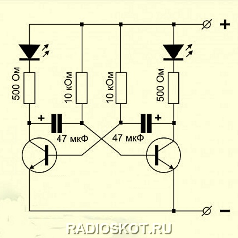
If you want to connect ordinary LEDs to the multivibrator– to make a “flashing light”, then buffer cascades are not required for this. They can be connected in series with collector resistors. This is due to the fact that the LED current is small, and the voltage drop across it during operation is no more than one volt. Therefore, they do not have any effect on the operation of the multivibrator. True, this does not apply to super-bright LEDs, for which the operating current is higher and the voltage drop can be from 3.5 to 10 volts. But in this case, there is a way out - increase the supply voltage and use transistors with high power, providing sufficient collector current.
Please note that oxide (electrolytic) capacitors are connected with their positives to the collectors of the transistors. This is due to the fact that on the bases of bipolar transistors the voltage does not rise above 0.7 volts relative to the emitter, and in our case the emitters are the minus of the power supply. But at the collectors of the transistors, the voltage changes almost from zero to the voltage of the power source. Oxide capacitors are not able to perform their function when connected with reverse polarity. Naturally, if you use transistors of a different structure (not N-P-N, but P-N-P structures), then in addition to changing the polarity of the power source, you need to turn the LEDs with the cathodes “up in the circuit”, and the capacitors with the pluses to the bases of the transistors.
Let's figure it out now What parameters of the multivibrator elements determine the output currents and generation frequency of the multivibrator?
What do the values of collector resistors affect? I have seen in some mediocre Internet articles that the values of collector resistors do not significantly affect the frequency of the multivibrator. This is all complete nonsense! If the multivibrator is correctly calculated, a deviation of the values of these resistors by more than five times from the calculated value will not change the frequency of the multivibrator. The main thing is that their resistance is less than the base resistors, because collector resistors provide fast charging of capacitors. But on the other hand, the values of collector resistors are the main ones for calculating the power consumption from the power source, the value of which should not exceed the power of the transistors. If you look at it, if connected correctly, they do not even have a direct effect on the output power of the multivibrator. But the duration between switchings (multivibrator frequency) is determined by the “slow” recharging of the capacitors. The recharge time is determined by the ratings of the RC circuits - base resistors and capacitors (R2C1 and R3C2).

A multivibrator, although it is called symmetrical, this refers only to the circuitry of its construction, and it can produce both symmetrical and asymmetrical output pulses in duration. The duration of the pulse (high level) on the collector VT1 is determined by the ratings of R3 and C2, and the duration of the pulse (high level) on the collector VT2 is determined by the ratings of R2 and C1.
The duration of recharging capacitors is determined by a simple formula, where Tau– pulse duration in seconds, R– resistor resistance in Ohms, WITH– capacitance of the capacitor in Farads:
Thus, if you have not already forgotten what was written in this article a couple of paragraphs earlier:
If there is equality R2=R3 And C1=C2, at the outputs of the multivibrator there will be a “meander” - rectangular pulses with a duration equal to the pauses between pulses, which you see in the figure.
The full period of oscillation of the multivibrator is T equal to the sum of the pulse and pause durations:
![]()
Oscillation frequency F(Hz) related to period T(sec) through the ratio:
As a rule, if there are any calculations of radio circuits on the Internet, they are meager. That's why Let's calculate the elements of a symmetrical multivibrator using the example .
Like any transistor stages, the calculation must be carried out from the end - the output. And at the output we have a buffer stage, then there are collector resistors. Collector resistors R1 and R4 perform the function of loading the transistors. Collector resistors have no effect on the generation frequency. They are calculated based on the parameters of the selected transistors. Thus, first we calculate the collector resistors, then the base resistors, then the capacitors, and then the buffer stage.
Procedure and example of calculating a transistor symmetrical multivibrator
Initial data:
Supply voltage Ui.p. = 12 V.
Required multivibrator frequency F = 0.2 Hz (T = 5 seconds), and the pulse duration is equal to 1 (one) second.
A car incandescent light bulb is used as a load. 12 volts, 15 watts.
As you guessed, we will calculate a “flashing light” that will blink once every five seconds, and the duration of the glow will be 1 second.
Selecting transistors for the multivibrator. For example, we have the most common transistors in Soviet times KT315G.
For them: Pmax=150 mW; Imax=150 mA; h21>50.
Transistors for the buffer stage are selected based on the load current.
In order not to depict the diagram twice, I have already signed the values of the elements on the diagram. Their calculation is given further in the Decision.

Solution:
1. First of all, you need to understand that operating a transistor at high currents in switching mode is safer for the transistor itself than operating in amplification mode. Therefore, there is no need to calculate the power for the transition state at the moments of passage of an alternating signal through the operating point “B” of the static mode of the transistor - the transition from the open state to the closed state and back. For pulse circuits built on bipolar transistors, the power is usually calculated for the transistors in the open state.
First, we determine the maximum power dissipation of the transistors, which should be a value 20 percent less (factor 0.8) than the maximum power of the transistor indicated in the reference book. But why do we need to drive the multivibrator into the rigid framework of high currents? And even with increased power, energy consumption from the power source will be large, but there will be little benefit. Therefore, having determined the maximum power dissipation of transistors, we will reduce it by 3 times. A further reduction in power dissipation is undesirable because the operation of a multivibrator based on bipolar transistors in low current mode is an “unstable” phenomenon. If the power source is used not only for the multivibrator, or it is not entirely stable, the frequency of the multivibrator will also “float”.
We determine the maximum power dissipation: Pdis.max = 0.8 * Pmax = 0.8 * 150 mW = 120 mW
We determine the rated dissipated power: Pdis.nom. = 120 / 3 = 40mW
2. Determine the collector current in the open state: Ik0 = Pdis.nom. / Ui.p. = 40mW / 12V = 3.3mA
Let's take it as the maximum collector current.
3. Let’s find the value of the resistance and power of the collector load: Rk.total = Ui.p./Ik0 = 12V/3.3mA = 3.6 kOhm
We select resistors from the existing nominal range that are as close as possible to 3.6 kOhm. The nominal series of resistors has a nominal value of 3.6 kOhm, so we first calculate the value of the collector resistors R1 and R4 of the multivibrator: Rк = R1 = R4 = 3.6 kOhm.
The power of the collector resistors R1 and R4 is equal to the rated power dissipation of the transistors Pras.nom. = 40 mW. We use resistors with a power exceeding the specified Pras.nom. - type MLT-0.125.
4. Let's move on to calculating the basic resistors R2 and R3. Their rating is determined based on the gain of transistors h21. At the same time, for reliable operation of the multivibrator, the resistance value must be within the range: 5 times more than the resistance of the collector resistors, and less than the product Rк * h21. In our case Rmin = 3.6 * 5 = 18 kOhm, and Rmax = 3.6 * 50 = 180 kOhm
Thus, the resistance values Rb (R2 and R3) can be in the range of 18...180 kOhm. We first select the average value = 100 kOhm. But it is not final, since we need to provide the required frequency of the multivibrator, and as I wrote earlier, the frequency of the multivibrator directly depends on the base resistors R2 and R3, as well as on the capacitance of the capacitors.
5. Calculate the capacitances of capacitors C1 and C2 and, if necessary, recalculate the values of R2 and R3.
The values of the capacitance of capacitor C1 and the resistance of resistor R2 determine the duration of the output pulse on the collector VT2. It is during this impulse that our light bulb should light up. And in the condition the pulse duration was set to 1 second.
Let's determine the capacitance of the capacitor: C1 = 1 sec / 100 kOhm = 10 µF
A capacitor with a capacity of 10 μF is included in the nominal range, so it suits us.
The values of the capacitance of capacitor C2 and the resistance of resistor R3 determine the duration of the output pulse on the collector VT1. It is during this pulse that there is a “pause” on the VT2 collector and our light bulb should not light up. And in the condition, a full period of 5 seconds with a pulse duration of 1 second was specified. Therefore, the duration of the pause is 5 seconds – 1 second = 4 seconds.
Having transformed the recharge duration formula, we Let's determine the capacitance of the capacitor: C2 = 4 sec / 100 kOhm = 40 µF
A capacitor with a capacity of 40 μF is not included in the nominal range, so it does not suit us, and we will take the capacitor with a capacity of 47 μF that is as close as possible to it. But as you understand, the “pause” time will also change. To prevent this from happening, we Let's recalculate the resistance of resistor R3 based on the duration of the pause and the capacitance of capacitor C2: R3 = 4 sec / 47 µF = 85 kOhm
According to the nominal series, the closest value of the resistor resistance is 82 kOhm.
So, we got the values of the multivibrator elements:
R1 = 3.6 kOhm, R2 = 100 kOhm, R3 = 82 kOhm, R4 = 3.6 kOhm, C1 = 10 µF, C2 = 47 µF.
6. Calculate the value of resistor R5 of the buffer stage.
To eliminate the influence on the multivibrator, the resistance of the additional limiting resistor R5 is selected to be at least 2 times greater than the resistance of the collector resistor R4 (and in some cases more). Its resistance, together with the resistance of the emitter-base junctions VT3 and VT4, in this case will not affect the parameters of the multivibrator.
R5 = R4 * 2 = 3.6 * 2 = 7.2 kOhm
According to the nominal series, the nearest resistor is 7.5 kOhm.
With a resistor value of R5 = 7.5 kOhm, the buffer stage control current will be equal to:
Icontrol = (Ui.p. - Ube) / R5 = (12v - 1.2v) / 7.5 kOhm = 1.44 mA
In addition, as I wrote earlier, the collector load rating of the multivibrator transistors does not affect its frequency, so if you do not have such a resistor, then you can replace it with another “close” rating (5 ... 9 kOhm). It is better if this is in the direction of decrease, so that there is no drop in the control current in the buffer stage. But keep in mind that the additional resistor is an additional load for transistor VT2 of the multivibrator, so the current flowing through this resistor adds up to the current of collector resistor R4 and is a load for transistor VT2: Itotal = Ik + Icontrol. = 3.3mA + 1.44mA = 4.74mA
The total load on the collector of transistor VT2 is within normal limits. If it exceeds the maximum collector current specified in the reference book and multiplied by a factor of 0.8, increase resistance R4 until the load current is sufficiently reduced, or use a more powerful transistor.
7. We need to provide current to the light bulb Iн = Рн / Ui.p. = 15W / 12V = 1.25 A
But the control current of the buffer stage is 1.44 mA. The multivibrator current must be increased by a value equal to the ratio:
In / Icontrol = 1.25A / 0.00144A = 870 times.
How to do it? For a significant increase in output current use transistor cascades built according to the “composite transistor” circuit. The first transistor is usually low-power (we will use KT361G), it has the highest gain, and the second must provide sufficient load current (let’s take the no less common KT814B). Then their transmission coefficients h21 are multiplied. So, for the KT361G transistor h21>50, and for the KT814B transistor h21=40. And the overall transmission coefficient of these transistors connected according to the “composite transistor” circuit: h21 = 50 * 40 = 2000. This figure is greater than 870, so these transistors are quite enough to control a light bulb.
Well, that's all!
Radio circuits for beginner radio amateurs
In this article we present several devices based on one circuit - an asymmetrical multivibrator using transistors of different conductivities.
flasher
Using this circuit, you can assemble a device with a blinking light bulb (see Fig. 1) and use it for various purposes. For example, install it on a bicycle to power turn lights, or in a lighthouse model, a signal light, or on a car or ship model as a flashing light.
The load of an asymmetrical multivibrator assembled on transistors T1, T2 is light bulb L1. The pulse repetition rate is determined by the capacitance value of capacitor C1 and resistors R1, R2. Resistor R1 limits the maximum flash frequency, and resistor R2 can be used to smoothly change their frequency. You need to start working from the maximum frequency, which corresponds to the top position of the resistor R2 slider in the diagram.
Please note that the device is powered by a 3336L battery, which produces 3.5 V under load, and the L1 light bulb is used at a voltage of only 2.5 V. Will it burn out? No! The duration of its glow is very short, and the thread does not have time to overheat. If the transistors have a high gain, then instead of a 2.5 V x 0.068 A light bulb, you can use a 3.5 V x 0.16 A light bulb. Transistors like MP35-MP38 are suitable for transistor T1, and transistors like MP39-MP42 are suitable for T2.
Metronome
If you install a loudspeaker in the same circuit instead of a light bulb, you will get another device - an electronic metronome. It is used in teaching music, for keeping time during physical experiments, and in photographic printing.
If you slightly change the circuit - reduce the capacitance of capacitor C1 and introduce resistor R3, then the pulse duration of the generator will increase. The sound will increase (Fig. 2). This device can serve as a house bell, a model horn, or a children's pedal car. (In the latter case, the voltage must be increased to 9 V.) And it can also be used for teaching Morse code. Only then, instead of the Kn1 button, you need to install a telegraph key. The sound tone is selected by capacitor C1 and resistor R2. The larger R3, the louder the sound of the generator. However, if its value is more than one kilo-ohm, then oscillations in the generator may not occur.

The generator uses the same transistors as in the previous circuit, and headphones or a head with a coil resistance of 5 to 65 Ohms are used as a loudspeaker.
Humidity indicator
An asymmetrical multivibrator using transistors of different conductivities has an interesting property: during operation, both transistors are either open or locked at the same time. The current consumed by the switched-off transistors is very small. This makes it possible to create cost-effective indicators of changes in non-electrical quantities, such as humidity indicators. The schematic diagram of such an indicator is shown in Figure 3. As can be seen from the diagram, the generator is constantly connected to the power source, but does not work, since both transistors are locked. Reduces current consumption and resistor R4. A humidity sensor is connected to sockets G1, G2 - two thin tinned wires 1.5 cm long. They are sewn to the fabric at a distance of 3-5 mm from each other. The resistance of the dry sensor is high. When wet it falls. The transistors open, the generator starts working. To reduce the volume, you need to reduce the supply voltage or the value of resistor R3. This humidity indicator can be used when caring for newborn babies.

Humidity indicator with sound and light signal
If you expand the circuit a little, the humidity indicator will emit light simultaneously with the sound signal - light bulb L1 will start to light up. In this case, as can be seen from the diagram (Fig. 4), two asymmetrical multivibrators on transistors of different conductivities are installed in the generator. One is assembled on transistors T1, T2 and is controlled by a humidity sensor connected to sockets G1, G2. The load of this multivibrator is lamp L1. The voltage from the collector T2 controls the operation of the second multivibrator, assembled on transistors T3, T4. It works as an audio frequency generator, and loudspeaker Gr1 is turned on at its output. If there is no need to give a sound signal, then the second multivibrator can be turned off.

The transistors, lamp and loudspeaker used in this humidity indicator are the same as in previous devices.
Siren simulator
Interesting devices can be built using the dependence of the frequency of an asymmetrical multivibrator on transistors of different conductivity on the base current of transistor T1. For example, a generator that simulates the sound of a siren. Such a device can be installed on a model of an ambulance, fire truck, or rescue boat.
The schematic diagram of the device is shown in Figure 5. In the initial position, the Kn1 button is open. Transistors are locked. The generator is not working. When the button is closed, capacitor C2 is charged through resistor R4. The transistors open and the multivibrator starts working. As capacitor C2 charges, the base current of transistor T1 increases and the frequency of the multivibrator increases. When the button is opened, everything repeats in the reverse order. The siren sound is simulated by periodically closing and opening the button. The rate of rise and fall of sound is selected by resistor R4 and capacitor C2. The siren tone is set by resistor R3, and the sound volume by selecting resistor R5. The transistors and loudspeaker are selected the same as in previous devices.

Transistor tester
Considering that this multivibrator uses transistors of different conductivities, you can use it as a device for testing transistors by replacement. The schematic diagram of such a device is shown in Figure 6. The circuit of a sound generator is taken as a basis, but a light pulse generator can be used with equal success.

Initially, by closing the Kn1 button, check the operation of the device. Depending on the type of conductivity, connect the transistor under test to sockets G1 - G3 or G4-G6. In this case, use switch P1 or P2. If there is sound in the loudspeaker when you press the button, then the transistor is working.
As switches P1 and P2, you can take toggle switches with two switching contacts. The figure shows the switches in the "Control" position. The device is powered by a 3336L battery.
Sound generator for testing amplifiers
Based on the same multivibrator, you can build a fairly simple generator for testing receivers and amplifiers. Its circuit diagram is shown in Figure 7. Its difference from a sound generator is that instead of a loudspeaker, a 7-step voltage level regulator is switched on at the output of the multivibrator.

E. TARASOV
Rice Y. CHESNOKOBA
YUT For skillful hands 1979 No. 8
This article describes a device designed simply so that a novice radio amateur (electrician, electronics engineer, etc.) can better understand the circuit diagrams and gain experience during the assembly of this device. Although it is possible that this simplest multivibrator, which is described below, can also find practical application. Let's look at the diagram:
Figure 1 - The simplest multivibrator on a relay
When power is applied to the circuit, the capacitor begins to charge through resistor R1, the contacts K1.1 are open, when the capacitor is charged to a certain voltage, the relay will operate and the contacts close, when the contacts are closed, the capacitor will begin to discharge through these contacts and resistor R2, when the capacitor is discharged to a certain voltage, the contacts will open and the process will then be repeated cyclically. This multivibrator works because the relay operating current is greater than the holding current. The resistance of the resistors CANNOT be changed within wide limits and this is a disadvantage of this circuit. The resistance of the power supply affects the frequency and because of this, this multivibrator will not work from all power sources. The capacitance of the capacitor can be increased, but the frequency of contact closure will decrease. If the relay has a second group of contacts and large capacitance values are used, then this circuit can be used to periodically automatically turn on/off devices. The assembly process is shown in the photos below:

Connecting resistor R2

Connecting a capacitor

Connecting resistor R1

Connecting the relay contacts to its winding

Connecting wires for power supply

You can buy a relay at a radio parts store or get it from old broken equipment. For example, you can desolder relays from boards from refrigerators:


If the relay has bad contacts, you can clean them a little.
In this article I will explain in detail how to make a multivibrator, which is the first circuit of almost every second radio amateur. As we know, a multivibrator is an electronic device that generates electrical oscillations close to rectangular in shape, which is reflected in its name: “multi-many”, “vibro-oscillation”. In other words, a multivibrator is a relaxation-type rectangular pulse generator with resistive-capacitive positive feedback, using a two-cascade amplifier closed in a positive feedback ring. When the multivibrator operates in self-oscillation mode, periodically repeating rectangular pulses are generated. The frequency of the generated pulses is determined by the parameters of the timing circuit, the properties of the circuit and its power supply mode. The frequency of self-oscillations is also influenced by the connected load. Typically, a multivibrator is used as a pulse generator of relatively long duration, which is then used to generate pulses of the required duration and amplitude.
Multivibrator circuit operation
Symmetrical transistor multivibrator
Schematically, the multivibrator consists of two amplifier stages with a common emitter, the output voltage of each of which is applied to the input of the other. When the circuit is connected to the power source Ek, both transistors pass through the collector points - their operating points are in the active region, since a negative bias is applied to the bases through resistors RB1 and RB2. However, this state of the circuit is unstable. Due to the presence of positive feedback in the circuit, the condition?Ku>1 is satisfied and the two-stage amplifier is self-excited. The regeneration process begins - a rapid increase in the current of one transistor and a decrease in the current of the other transistor. Let, as a result of any random change in the voltages at the bases or collectors, the current IK1 of transistor VT1 increase slightly. In this case, the voltage drop across resistor RK1 will increase and the collector of transistor VT1 will receive an increase in positive potential. Since the voltage on capacitor SB1 cannot change instantly, this increment is applied to the base of transistor VT2, turning it off. At the same time, the collector current IK2 decreases, the voltage at the collector of transistor VT2 becomes more negative and, transmitted through capacitor SB2 to the base of transistor VT1, opens it even more, increasing the current IK1. This process proceeds like an avalanche and ends with transistor VT1 entering saturation mode, and transistor VT2 entering cutoff mode. The circuit enters one of its temporarily stable equilibrium states. In this case, the open state of transistor VT1 is ensured by a bias from the power source Ek through resistor RB1, and the locked state of transistor VT2 is ensured by the positive voltage on capacitor SB1 (Ucm = UB2 > 0), which is connected through the open transistor VT1 to the base-emitter gap of transistor VT2.
To build a multivibrator The radio components we need are:1. Two KT315 type transistors.
2. Two electrolytic capacitors 16V, 10-200 microfarads (The smaller the capacitance, the more often the blinking).
3. 4 resistors with a nominal value of: 100-500 ohms, 2 pieces (if you set 100 ohms, the circuit will work even from 2.5V), 10 ohms, 2 pieces. All resistors are 0.125 watt.
4. Two dim LEDs (Any color except white).
Lay6 format printed circuit board. Let's start manufacturing. The printed circuit board itself looks like this:

We solder two transistors, do not confuse the collector and base on the transistor - this is a common mistake.

We solder capacitors 10-200 Microfarads. Please note that 10 volt capacitors are highly undesirable for use in this circuit if you will be supplying 12 volt power. Remember that electrolytic capacitors have polarity!


The multivibrator is almost ready. All that remains is to solder the LEDs and input wires. A photo of the finished device looks something like this:

And to make everything clearer to you, here’s a video of a simple multivibrator in action:
In practice, multivibrators are used as pulse generators, frequency dividers, pulse shapers, contactless switches, and so on, in electronic toys, automation devices, computing and measuring equipment, in time relays and master devices. I was with you Boil-:D . (material was prepared upon request Demyan" a)
Discuss the article MULTIVIBRATOR